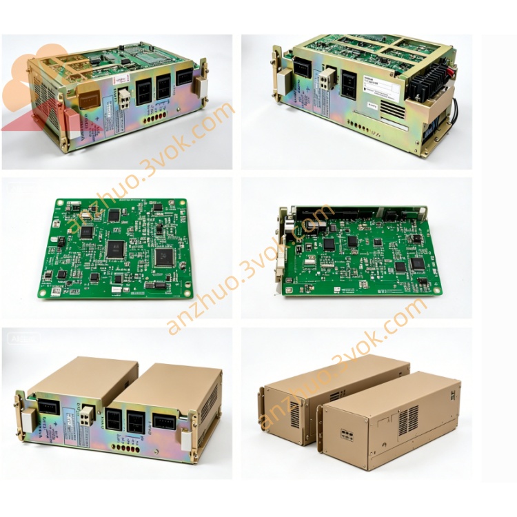
JANCD-TU01
Description
1. General Information
2. Specifications
2.1 Electrical Ratings
Logic Supply: 24 VDC ±10%, 0.3 A typical
I/O Rating: 24 VDC, 50 mA per point (max.)
Isolation: Photocoupler isolation between field and controller logic
Power Consumption: ≤8 W
2.2 Environmental Conditions
Operating Temperature: 0°C to +40°C
Storage Temperature: −10°C to +60°C
Humidity: 5%–80% RH, non-condensing
Vibration: ≤0.5 G (10–500 Hz)
Altitude: Up to 1,000 m
2.3 I/O Configuration
Digital Inputs: 16 points (24 VDC sink/source selectable)
Digital Outputs: 8 points (relay or transistor type, depending on revision)
Safety Inputs: Emergency stop, servo enable, limit switches
Signal Type: NPN/PNP compatible (jumper selectable)
3. System Compatibility
Compatible Controllers: YASNAC XRC, ERC series
Compatible Main Boards: JANCD-CP04B, JANCD-CP03B
Application: Material handling, welding, assembly, and general automation
Mounting: Standard slot in XRC/ERC controller cabinet
4. Connectors and Terminals
CN1 (Controller Bus Interface)
50-pin flat-cable connector for communication with CPU board
Transmits I/O status, safety signals, and configuration data
TB1 (Field Wiring Terminal Block)
Screw terminals for all digital inputs, outputs, and safety signals
Terminal assignment includes 24 VDC, 0 V, input common, output common, E-stop, and limits
CN2 (24 VDC Power Input)
Connects to controller internal 24 VDC supply for board logic
5. LED Indicators
PWR: Green, lit when 24 VDC power is normal
IN01–IN16: Green, lit when corresponding input is active
OUT01–OUT08: Green, lit when corresponding output is active
ALM: Red, lit when safety signal fault or communication error occurs
6. Installation Instructions
Power off the controller and wait 5 minutes for capacitors to discharge.
Use an anti-static wristband to prevent ESD damage.
Insert the board into the designated slot and secure with four M3 screws (torque 0.8–1.0 N·m).
Connect CN1 to the CPU board with the provided flat cable.
Wire field devices to TB1 according to the terminal assignment.
Connect 24 VDC power to CN2.
Restore power and verify LED indicators: PWR on, no ALM.
7. Safety Features
Hardware emergency stop interface (Category 3 compliant)
Overcurrent protection on I/O circuits
Input/output short-circuit detection
Isolation between field side and controller logic
Safety signal monitoring with alarm output
8. Maintenance and Troubleshooting
Maintenance
Inspect terminal block screws quarterly for tightness.
Clean dust from the board with low-pressure dry compressed air.
Check flat cable connections annually.
Troubleshooting
PWR LED off: Check CN2 24 VDC supply and wiring.
ALM LED on: Verify E-stop circuit, limit switches, or CN1 cable.
Input LED not lit: Check field device wiring and common voltage.
Output not activating: Verify output common and load wiring.
9. Ordering Information
Model Number: JANCD-TU01
Replacement Part Number: 161540-1
Manufacturer: Yaskawa Electric Corporation (Motoman Robotics Division)
Country of Origin: Japan
Warranty: 12 months under normal operating conditions
Get a Quote