JZNC-MRJ09
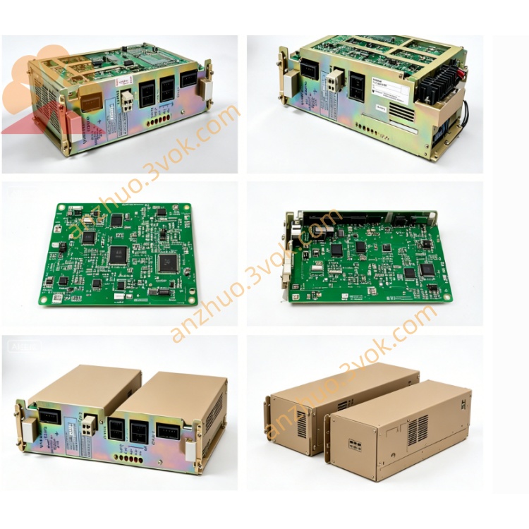
JZNC-MRJ09 is an original Yaskawa Motoman dedicated servo communication interface mainboard, specially configured for DX series robot control cabinet, functioning as core bus conversion board between robot main CPU unit and each axis servo amplifier module. It realizes real-time transmission of motion command, position instruction, speed control signal and servo feedback data via proprietary internal robot bus protocol, and processes fault feedback signal sent back from each servo drive. This board is installed on the standard backplane slot inside robot electric cabinet and matches supporting base rack of MRK series chassis; no independent original English pamphlet is released separately, all technical content is compiled from official DX robot hardware maintenance specification of Yaskawa.
Description
1. General Overview
JZNC-MRJ09 is an original Yaskawa Motoman dedicated servo communication interface mainboard, specially configured for DX series robot control cabinet, functioning as core bus conversion board between robot main CPU unit and each axis servo amplifier module. It realizes real-time transmission of motion command, position instruction, speed control signal and servo feedback data via proprietary internal robot bus protocol, and processes fault feedback signal sent back from each servo drive. This board is installed on the standard backplane slot inside robot electric cabinet and matches supporting base rack of MRK series chassis; no independent original English pamphlet is released separately, all technical content is compiled from official DX robot hardware maintenance specification of Yaskawa.
2. Electrical and Ambient Parameters
The rated input working power is DC24V supplied by internal cabinet switching power source, total rated working current below 0.8A under full-load continuous operation condition. Onboard built-in slow-blow safety fuse with rated specification 3.15A for input overcurrent protection to avoid circuit burnout caused by external short-circuit of signal line.
Permissible continuous working ambient temperature ranges from 0°C to +55°C; non-operating storage temperature after power cut is between -20°C and +70°C. Applicable environment relative humidity keeps within 5%~90% without dew condensation. Installation site must stay away from heavy oil mist, corrosive chemical gas, intense mechanical vibration and strong high-frequency electromagnetic interference, fixed on cabinet backplane via locking screws. Protection grade of the board is IP20 for internal cabinet application only.
3. Connector Functional Description
One group of internal backplane gold finger connector is used for plugging onto MRK series base rack, responsible for bidirectional high-speed bus communication with robot main control CPU board, receiving all axis motion instructions and sending servo actual position, speed and fault state data back to main controller. Loose insertion or pin oxidation here will trigger whole robot servo communication failure alarm.
Multiple groups of external multi-core signal connectors connect dedicated servo cables leading to each axis servo driver, distributing split servo enable signal, analog speed command and encoder feedback signal to corresponding single-axis amplifier respectively. Wrong wiring or short circuit of external cable will blow onboard protective fuse and lead to partial or all axes servo disable.
A reserved auxiliary terminal block is designed for external safety interlock signal input, receiving cabinet safety door lock signal and peripheral emergency stop series signal to cooperate with system safety circuit for servo power cut-off protection when abnormal safety status occurs.
4. Installation and Replacement Operation Procedure
Completely disconnect three-phase AC main power supply of entire robot control cabinet, wait at least 5 minutes for residual electric charge inside cabinet capacitor to fully discharge to prevent electric shock and onboard component breakdown during disassembly work.
Mark all external signal cables and internal backplane plug position one by one before unplugging all connecting wires, record original wiring sequence completely for subsequent reinstallation reference. Unscrew fixed locking screws at board edge then pull out faulty JZNC-MRJ09 smoothly along backplane slot direction.
Align new replacement board with base rack mounting notch and insert fully into backplane slot, tighten fixing screws steadily to avoid loose vibration after long-time operation. Recover all signal cables strictly following pre-recorded marking order without cross connection or vacant terminal misconnection. After all wiring finished, close cabinet door and switch on main power supply, complete system power-on self-test, confirm no servo communication error alarm appears, execute single-axis jog movement test sequentially to verify normal servo response before formal robot production operation.
5. Common Fault Troubleshooting Guidance
All axes pop up servo communication error after power-on: first check DC24V input voltage of the board, inspect onboard fuse integrity and plug tightness between MRJ09 board and backplane base rack; check breakage of common bus cable connected to servo drivers.
Individual single axis cannot jog with servo no-enable alarm: test continuity of corresponding axis external servo cable, verify relevant servo amplifier power supply normal state and connector pin corrosion condition.
Intermittent random axis servo drop-out during running: check loose wiring of signal connector and abnormal ambient temperature exceeding upper limit, eliminate peripheral electromagnetic interference source nearby cabinet.
Board indicator lamp fully off after power input: measure DC24V power supply output from cabinet internal power unit and inspect open-circuit of input power wiring.
6. Safety Operation Precautions
It is strictly forbidden to arbitrarily modify original onboard circuit layout, replace standard rated fuse with non-standard spare part and alter factory-defined pin assignment of each connector; unauthorized modification will damage robot bus protocol circuit and result in permanent burnout of CPU mainboard or multi-axis servo drives. All disassembly, replacement and maintenance work of JZNC-MRJ09 must be performed by professional maintenance technicians familiar with Yaskawa DX robot hardware structure. Always cut off total cabinet main power before any onboard maintenance and wiring adjustment.
Get a Quote