JZNC-NIF01B
Description
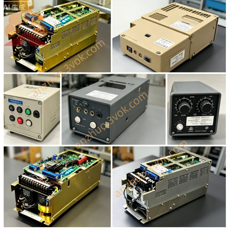
1. Product Overview
Compatible Robot Models
2. Electrical Rating
Power input: DC24V from cabinet internal power supply CPS-NX1 via backplane gold finger
Onboard fuses: F1 & F2, 3.15A 250V quick-blow fuse, for 24VDC I/O loop overcurrent protection
I/O Specification: Total 40DI /40DO (NPN sink type DC24V), 4 external terminal connectors for field wiring split into System I/O and User I/O two groups
System I/O: Predefined fixed signals for positioner, external controller interlock
User I/O: Free programmable digital signal for peripheral fixture, sensor, conveyor trigger
Working logic voltage: Internal logic +5V powered from cabinet system power source
3. Core Functional Description
Internal PCI Bus Communication: Connect to CPU mainboard via cabinet backplane PCI bus for program, parameter, motion command data transmission.
High-Speed Serial Servo Link: Real-time serial communication with SGDR-AXA01A axis control board for multi-axis servo position, speed feedback data exchange.
Dual-channel Safety Circuit: Built redundant dual safety loop for E-stop, safety door interlock signal routing, core component of robot safety control system.
I/O Signal Conversion & Isolation: Opto-isolation circuit between internal logic and external field I/O to suppress surge and EMI interference from field equipment.
Parameter Storage: Stores robot mechanical parameters, tool data, teach programs; data backup mandatory before board replacement.
4. Environmental Parameter
Operating temperature: 0℃ ~ +55℃; Storage temperature: -20℃ ~ +70℃
Humidity: 10%~90%RH non-condensation, IP20 indoor cabinet installation only
Avoid oil mist, corrosive gas, heavy vibration and strong electromagnetic field near welding/inverter equipment.
Weight: Approx 1.27kg per single board assembly.
5. Replacement & Installation Procedure (OEM Standard Steps)
Full cut off cabinet AC main power, wait ≥10min for internal capacitor residual voltage discharge.
Enter Maintenance Mode via teach pendant, insert CF card and complete full backup of robot programs + all system parameters (critical step).
Mark all external I/O cable pin assignment, disconnect all field wiring from 4 I/O terminals on NIF01B.
Remove 2 fixing screws on board edge, pull out faulty NIF01B straight from backplane slot.
Check rotary DIP switch on new NIF01B, set to identical code value as original old board.
Insert new board into designated backplane slot, lock fixing screws tightly.
Restore all external I/O wiring strictly per pre-marked sequence, no cross connection.
Power on cabinet, boot into Maintenance Mode again, restore backup data from CF card into new board.
Switch to Normal Mode, execute full-axis jog test and peripheral I/O point-to-point test to confirm no communication/alarm fault.
6. Common Fault Diagnosis
Robot boots with I/F COMM ERROR / SAFETY LOOP ALARM: Poor PCI gold finger contact; clean slot pins or replace NIF01B; check blown F1/F2 fuse caused by external I/O short-circuit.
Partial DI/DO points invalid: Corroded terminal pin or optocoupler damage on NIO01 I/O sub-board; check external 24V field power short.
All servo axes unable to initialize: Lost serial communication between NIF01B and AXA01A axis board, replace faulty interface board.
Parameter lost randomly after power cycle: Onboard backup battery aging on NIF01B PCB, replace internal lithium battery.
7. Safety Warning
Never modify onboard original circuit wiring arbitrarily; damage will cause total system crash and servo board cascade burnout.
All maintenance/replacement must be operated by certified Yaskawa maintenance personnel.
Always backup full robot data before any board swap, missing parameters will lead to robot axis zero-point loss and collision risk.
Get a Quote