JZNC-RK32
Description
1. General Introduction
2. Electrical & Hardware Specifications
Input Power: DC24V ±10V, supplied from system internal switching power supply module
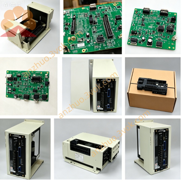
Onboard configuration: built-in main CPU chip, system program ROM, user RAM memory, servo bus drive circuit, I/O signal processing circuit and dedicated panel communication interface
External connectors: multi-pin terminal sockets for servo drive bus, operator panel cable, machine peripheral I/O terminal block
PCB dimension: approx 310mm × 225mm; net weight ~0.95kg
Working ambient voltage fluctuation tolerance: ±10% for rated input power
3. Core Functional Description
NC Motion Calculation: Process G-code machining programs, generate position commands for each feed axis & spindle servo drive, realize interpolation control of linear/circular machining paths
PLC Logical Control: Execute built-in machine ladder logic, manage peripheral auxiliary equipment including coolant pump, spindle brake, automatic tool changer, door interlock and limit switch signal processing
HMI Data Interaction: Transmit coordinate, program, parameter and alarm data bidirectionally with JZNC-OP15/OP16 front operation panel via dedicated communication cable
Parameter Storage & Management: Store system servo parameters, machine geometry data, tool compensation values and user NC part programs on onboard memory chip
Fault self-diagnosis: Detect abnormal signals of servo, I/O circuit and communication link, send corresponding alarm codes to display on operator panel once fault occurs
4. Environmental Operation Requirements
Operating temperature: 0℃ ~ +55℃ inside sealed CNC control cabinet; storage temperature: -25℃ ~ +75℃
Humidity range: 10%~88%RH without condensation; strictly avoid cutting fluid vapor, oil mist, conductive dust and corrosive gas inside cabinet
Anti-interference requirement: Keep away from high-power contactor, inverter and welding equipment to prevent strong electromagnetic surge damage to onboard circuit
5. Replacement & Installation Steps
Cut off total machine AC input power completely, wait more than 10 minutes for cabinet internal power supply capacitor full discharge
Mark definition for all plug-in connectors on RK32 board before unplugging servo bus, panel communication and I/O wiring one by one
Remove fixed mounting screws on PCB fixing base and extract original JZNC-RK32 board from cabinet card slot
Insert new replacement board into original installation slot and fasten all fixing screws tightly
Recover all connectors strictly following pre-marked labels; power on equipment after wiring completion, verify system boot-up, panel communication and axis jog function before formal production
6. Common Fault Troubleshooting
System no boot / operator panel no display: Inspect DC24V input power supply, loose plug connectors and onboard fuse burnout of RK32 mainboard
Panel display normal but axis cannot jog: Check servo bus wiring contact failure or mainboard servo output circuit damage
Random system alarm & intermittent communication loss: Troubleshoot poor cabinet heat dissipation leading to overheating or aged onboard memory component
7. Safety Notes
Forbid plug/unplug onboard connectors under powered status to avoid instantaneous overvoltage burning PCB circuit
All maintenance and component replacement must be operated by professional maintenance personnel familiar with Yasnac LX3/MX3 system
Do not arbitrarily modify original onboard circuit wiring or replace non-standard electronic components on mainboard
Get a Quote