JZNC-OP16
Description
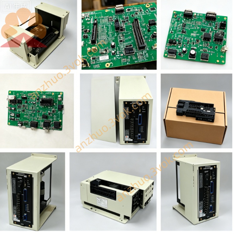
1. General Overview
2. Electrical Specifications
Input Power: AC100V ±10%, 50/60Hz, supplied from machine control cabinet power unit
Rated Power Consumption: approx 78W under full-load operating condition
Display: built-in green monochrome CRT driven by onboard JANCD-I0O2 PCB circuit
Rear Interface: two dedicated multi-pin connectors for NC bus signal & power wiring
Overall dimension: 228mm(W) × 205mm(H) × 38mm(D); net weight: ~2.7kg
3. Front Panel Layout & Key Zones
Left Area: Red mushroom-shaped emergency stop button + system power control switches
Central Region: Embedded CRT window for NC program content, real-time axis coordinates, system parameter values and fault alarm codes display
Right-side full-function keypad split into four functional groups:
Mode Select Keys: AUTO, MDI, JOG, ZRN, Single Block, Dry Run mode switching
Program Edit Keys: numeric input, G/M/S/T address codes, INSERT/DELETE/ALTER for NC program modification
Manual Operation: each axis jog directional keys, feedrate override dial & spindle speed adjustment knob
Aux Control Keys: spindle ON/OFF, coolant switch, machine lock, diagnostic shortcut buttons
4. Core Functional Features
NC Program Management: Create, edit, store and recall part machining programs directly from panel keypad
Manual Axis Control: JOG incremental movement, mechanical origin return and workpiece edge alignment for all feed axes
Parameter Configuration: Check, edit & save servo parameters, workpiece coordinate offset and tool wear compensation data
Runtime Monitoring: Real-time CRT display of actual axis position, spindle RPM, servo running status and peripheral I/O signal status
Fault Alarm Prompt: Auto popup error codes on screen once servo, spindle or peripheral circuit malfunction occurs for maintenance reference
5. Environmental Operating Requirements
Continuous operating temperature: 0℃ ~ +50℃; storage temperature: -20℃ ~ +70℃
Ambient humidity: 10%~85%RH, no dew condensation allowed
Installation restriction: Mount inside machine operation cabinet; avoid cutting fluid splash, heavy oil mist, corrosive gas, intense mechanical vibration and strong electromagnetic interference from welding/inverter equipment
6. Disassembly & Replacement Procedure
Cut off complete machine main AC power, wait minimum 5 minutes for CRT high-voltage capacitor full discharge to prevent electric shock hazard
Mark wiring definition for every rear cable before disconnecting power & signal connectors sequentially
Unscrew surrounding fixing fasteners and extract OP16 unit from cabinet embedded slot
Fix new replacement panel into original mounting position and tighten all fixing screws securely
Reconnect all cables strictly following previous marked wiring labels; complete power-on test for display and all key functions before trial machining
7. Common Fault Troubleshooting
No CRT display after power-on: Verify AC100V input voltage, check internal power fuse integrity and loose solder joints on built-in JANCD-I0O2 board
Single key no response: Inspect damaged membrane switch contact or broken internal keypad wiring
Full communication loss with NC mainboard: Troubleshoot open-circuit or poor contact of rear main multi-core communication cable
8. Safety Regulations
Prohibit unauthorized disassembly of internal CRT high-voltage components and arbitrary circuit modification; residual high voltage remains inside display module long after power cut-off
All internal maintenance work must be performed by professional technicians familiar with Yasnac LX3/MX3 hardware structure
Always disconnect total machine power before any panel inspection, repair or component replacement
Get a Quote