1. General Specification
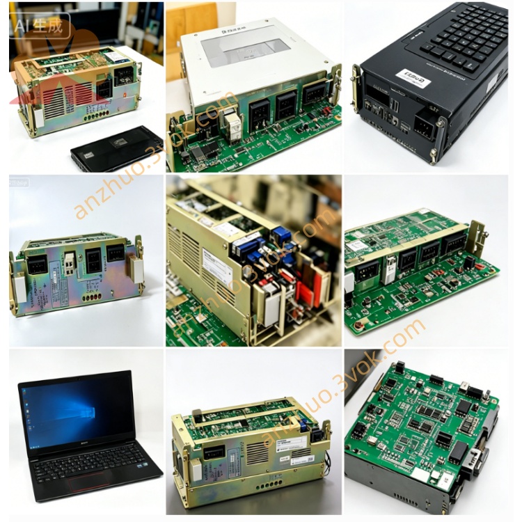
JZNC-MRK09 is the original Yaskawa Motoman main system backplane rack exclusively matched for DX series robot controller, serving as the core carrier and bus distribution baseboard for JZNC-MRJ09 servo communication board, CPU master board, I/O interface cards and other plug-in control boards inside cabinet. It integrates built-in power distribution copper traces and dedicated system bus wiring, realizing centralized DC24V power supply distribution and high-speed internal bus interconnection between all inserted functional circuit boards. Multiple suffix versions like MRK09-1 / MRK09-2 / MRK09-19 / MRK09-21 correspond to different slot quantities of the backplane for varied robot axis configuration options. This backplane has no separate independent original paper manual; all technical data is sorted from Yaskawa DX robot official maintenance documentation.
2. Electrical & Environmental Parameters
Rated input power supply: DC24V ±10% from cabinet internal switching power source; total maximum allowable output load current is 6A for all slot power distribution. Built-in distributed overcurrent protection circuit on PCB power track to prevent cascaded board burnout caused by short-circuit of any inserted card.
Working ambient temperature range: 0℃ ~ +55℃ continuous operation; storage temperature after power-off: -20℃ ~ +70℃. Applicable working humidity: 10%~90%RH non-condensation; installation location must avoid oil mist, corrosive gas, severe vibration and strong electromagnetic interference, fixed vertically inside robot electric cabinet by four corner mounting screws. Protection class IP20 for indoor cabinet installation only.
3. Structural & Connector Function Description
3.1 Gold finger card slots
Multi-group standard slot gold fingers are pre-routed on PCB: each slot includes DC24V power pins, system control bus pins, safety interlock signal pins and ground pins. All inserted control boards (MRJ09, CPU, I/O board etc.) obtain working power and system bus communication via corresponding slot gold fingers. Poor contact of slot pins will trigger power loss or intermittent communication failure of the plugged board.
3.2 External terminal power connector
Side-mounted multi-pin terminal block is used for DC24V main power input from cabinet power unit, distributing power to every slot’s internal circuit via onboard printed wiring. All safety loop common signals of each plug-in board converge on the backplane’s shared signal circuit to form whole-system safety interlock logic of emergency stop and cabinet door interlock.
3.3 Common ground circuit
Integrated full-board grounding copper layer for anti-interference, all inserted boards’ signal ground connects uniformly to backplane common ground then links cabinet PE grounding terminal, effectively restraining signal distortion caused by ground potential difference.
4. Installation & Replacement Procedures
Cut off the total 3-phase AC input power of robot control cabinet completely, wait minimum 10 minutes for internal large-capacity capacitor residual voltage full discharge to avoid electric shock and component damage risk.
Mark the installation slot position and cable sequence of all plugged circuit boards one by one, pull out each functional board from backplane slots sequentially after labeling all external wiring.
Unscrew four fixed locking screws of MRK09 backplane, take out old backplane smoothly from cabinet fixed bracket.
Fix new JZNC-MRK09 on installation position with fastening screws, insert each control board into original marked slot in order, recover all external power and signal wiring strictly according to pre-marked sequence without misconnection or vacant wiring.
Close cabinet door, switch on main power supply, execute system power-on self-check, confirm no power fault or bus communication error alarm; perform full-axis jog test to verify all boards and servo axes run normally before formal production startup.
5. Common Fault Diagnosis
All inserted boards no power indication after power-on: Check DC24V input voltage at backplane main terminal, inspect open circuit of input power cable and backplane main power track burnout.
Single plug-in board abnormal power-off or communication lost: Clean corresponding slot gold finger for oxidation/dirt, test short-circuit of the inserted board leading to backplane slot overcurrent protection cut-off.
Random intermittent communication breakdown of whole system: Check loose backplane fixing screws causing slot poor contact, inspect cabinet ambient over-temperature or surrounding strong EMI interference source.
Partial slots no DC24V output: Confirm partial power track breakage or hidden open-circuit on backplane PCB due to long-term aging.
6. Safety Precautions
Forbid arbitrary cutting or modifying onboard PCB wiring, changing original pin definition of slots and terminal block; unauthorized circuit modification will damage whole robot bus architecture and cause permanent burnout of multiple control boards. All disassembly, replacement and maintenance work must be completed by certified professional robot maintenance technicians. Always cut off cabinet main power before any backplane maintenance operation.
Get a Quote