
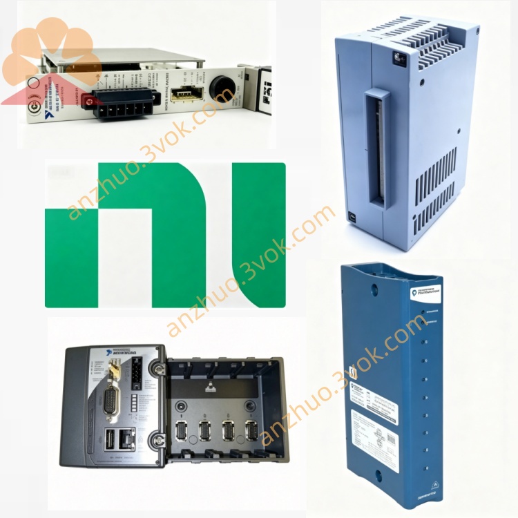
NI PXIe-8106 Low-power PXIe Embedded Controller
Description
Product Introduction
The NI PXIe-8106 is a 3U single-slot PXIe embedded controller. As the main core of the PXI test system, it integrates a high-performance processor, memory, and storage units, and can independently drive the entire PXI chassis to operate without the need for an external desktop computer. It is specifically designed for automated testing, real-time control, and high-speed data processing scenarios, balancing the operating capabilities of general operating systems and real-time operating systems. Its stability and computing performance can meet the long-term continuous working requirements of industrial mass production testing, signal analysis, and equipment control.
Model Interpretation
PXIe represents that the device adopts the PXI Express bus architecture and follows the 3U single-slot mechanical standard, and is compatible with all series of standard PXIe chassis slots. 8106 belongs to the NI PXI embedded controller series number, positioning as a mid-range high-performance main control unit, responsible for the scheduling of the entire chassis equipment, data processing, program execution, and peripheral management. This device is a complete computing unit, integrating a processor, memory, hard disk, and various peripheral interface, different from FPGA, acquisition, and counting function modules. Technical Specifications
Core computing unit
Equipped with a standard embedded processor, it supports multi-threaded computing and can run test programs, data analysis software, and device management programs smoothly. The board is pre-installed with standard memory, which can be expanded according to usage requirements to meet the memory capacity demands for large programs and parallel multi-tasking. A high-speed solid-state drive is built-in for installing the system, application software, and local storage of test data. The read and write speed is stable, suitable for high-frequency data reading and writing scenarios.
Bus and interface performance
Uses the PXIe Gen2 bus, which can fully utilize the bandwidth of the chassis backplane and achieve high-speed data interaction with various modules such as acquisition, FPGA, timing, etc. The controller is equipped with a gigabit Ethernet interface, supporting networking remote control, data upload, and multi-chassis interconnection. It is equipped with general USB interfaces, video output interfaces, audio interfaces, and serial ports, allowing for direct connection to displays, keyboards, mice, peripherals, and third-party devices.
Electrical and environmental parameters
The module is of 3U standard size and is compatible with the conventional PXIe chassis installation specifications. The overall power consumption is reasonable, and when combined with the chassis cooling system, it can operate continuously for a long time. The standard operating temperature range is 0 degrees Celsius to 55 degrees Celsius. It has industrial-level anti-interference and anti-static capabilities, suitable for complex electromagnetic environments such as workshops and laboratories.
Interface and communication configuration
Host bus interface
Connects to the chassis backplane through the PXIe Gen2 bus to complete data interaction, command issuance, and status collection with all functional modules in the chassis, supporting PXI backplane clock, trigger signal routing, and ensuring the synchronization of the entire system timing.
Front panel peripheral interface
The panel integrates various general peripheral interfaces, including a video output interface for connecting displays to achieve local screen display; a gigabit Ethernet interface for local network communication, remote access, and data transmission; multiple USB interfaces for connecting keyboards, mice, removable storage, printers, etc.; and also includes an audio interface and serial communication interface to meet the connection requirements for external analog audio devices and serial devices.
Driver and software communication
Compatible with Windows universal operating system and NI real-time operating system. The system comes with complete hardware drivers that can automatically identify all PXI modules in the chassis. Supports a full range of NI software suites such as NI-MAX, LabVIEW, TestStand, and is compatible with third-party development tools such as C/C++ and Python. It can achieve remote desktop, remote program deployment, and remote equipment operation through Ethernet.
Core functions
As the main control core of the PXI system, it is responsible for managing the hardware resources of the entire chassis, scheduling tasks, and executing programs, replacing the external computer to achieve integrated deployment. It has high-speed data computing and local storage capabilities, capable of completing test data computing, result analysis, log saving, etc. It supports two usage modes: local operation and remote network control, suitable for on-site debugging and remote operation scenarios. It fully complies with all series of PXI functional modules and can be combined with acquisition, FPGA, digital IO, timing synchronization, etc. to build an integrated test platform. Supports long-term continuous operation and has abnormal self-detection capabilities to ensure the stable operation of unmanned automated production lines. Applicable scenarios
In the field of automated mass production testing, as the main control unit of the production line PXI test station, it runs the test sequence, manages the hardware and generates test reports. In the signal monitoring and analysis scenario, it is combined with the acquisition module to complete real-time data processing, spectrum analysis and data recording. In the industrial equipment control field, it relies on the real-time system to achieve high-precision equipment linkage and logical control. In laboratory research and prototype verification, it serves as the main control to run algorithm programs and control various modular instruments to complete experiments. In the multi-box distributed system, through Ethernet networking, multiple sets of PXI devices can work collaboratively and be uniformly managed.
User and Maintenance Instructions Instruction Manual
When the equipment is powered off, insert the standard 3U PXIe chassis empty slot, tighten the fixing screws, and check that the internal backplane connection is normal before powering on. Connect the display, keyboard, mouse, network cable, etc. as per the usage requirements, complete the installation and configuration of the operating system and application software. Before running the test program, identify and confirm the normal status of all modules in the chassis through NI-MAX. When enabling the real-time control function, follow the software instructions to complete the system mode switching and parameter configuration. During the equipment operation, avoid frequent power off and vibration. Ensure that the card snap is secure when connecting the network interface cable.
Maintenance Instructions
Regularly use a dry soft cloth to wipe all interfaces and the exterior of the panel, clean the dust, keep the interfaces in good contact, and strictly prohibit spilling liquids onto the equipment surface. Regularly organize the system disk space, clean useless logs and cache files to ensure the efficiency of hard disk reading and writing. When running continuously for a long time, regularly check the cooling status of the chassis to avoid poor cooling due to dust accumulation. When the equipment is idle for a long time, place it in a dry environment ranging from -20°C to 60°C with a relative humidity of less than 60%. When the equipment has abnormal startup, malfunction of external devices, or communication interruption, prioritize checking the power supply, wiring, and system service status; for system operation lag, clear background programs, check disk and memory usage.
Get a Quote