
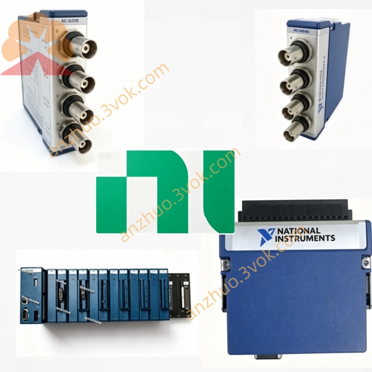
NI PXIe-8840 Mid-Range PXIe Embedded Controller
Description
Product Introduction
The NI PXIe-8840 is a 3U single-slot PXIe embedded main controller, which needs to be installed in the system slot of the chassis for use. It is the core control unit of the entire PXIe equipment. The device is equipped with a quad-core high-performance processor and integrates multiple peripheral interface circuits. It can independently run the operating system and various testing applications, coordinate the management of all functional modules in the chassis, and does not require an external computer. The entire machine takes into account both general computing and real-time control capabilities, and is suitable for scenarios that require long-term stable operation such as industrial automation, radio frequency testing, and precise measurement.
Model Interpretation
PXIe represents that the device adopts the PXI Express bus and follows the 3U single-slot mechanical standard. 8840 belongs to the NI embedded controller series number, positioning it as the main control unit of the chassis, responsible for task scheduling, data computing, and peripheral management, and is different from the coprocessing module, undertaking the core control work of the entire platform. Technical Specifications
Core hardware
The processor is an Intel quad-core eight-thread model with a base frequency of 2.6 GHz and a maximum turbo frequency of 3.4 GHz. It is equipped with 6 megabytes of high-speed cache. The standard configuration includes 4 gigabytes of memory, which can be expanded up to 8 gigabytes. It uses SATA interface storage media. The regular version comes with a mechanical hard drive, while the wide-temperature version is equipped with a solid-state drive. The bus adopts the PXIe Gen2 x8 specification, enabling high-speed data interaction through the chassis back panel. The module is powered by the chassis bus, with a typical power consumption of 25 watts. Environmental parameters
The standard model operates within a temperature range of 5 degrees Celsius to 50 degrees Celsius, while the wide-temperature model can function in an environment ranging from 0 degrees Celsius to 55 degrees Celsius. The required humidity for the working environment is 10% to 90%, without condensation, and the normal working altitude limit is 2,000 meters. It has industrial-grade electromagnetic protection capabilities.
Interface and Communication Configuration
Box Bus Interface
Connect to the backplane bus of the PXIe box to access the box clock, trigger and other synchronization resources, complete the instruction transmission and data interaction with all internal modules, and ensure the coordination of multiple devices' timing.
Front Panel Interface
The panel is equipped with two video output interfaces, supporting the external connection of dual monitors. It integrates two gigabit Ethernet interfaces, enabling networking communication, remote access and multi-device interconnection. There are six sets of USB interfaces, including high-speed and conventional specifications, for connecting keyboards, mice, mobile storage and other peripherals. It comes with a standard RS-232 serial port that can interface with traditional serial industrial equipment. It also has an independent reset button, status indicator lights and expansion slots, and integrates GPIB-related control interfaces.
Driver and Software Communication
The device can run on Windows systems, or install the LabVIEW real-time operating system as needed. The system comes with complete hardware drivers that can automatically identify all PXIe modules in the box. It is fully compatible with NI-MAX, LabVIEW, TestStand and other supporting software, and supports programming and functional development using multiple mainstream programming languages.
Core Functions
As the main control of the box, it uniformly schedules all hardware modules, executes test processes, data calculations and device control tasks. The quad-core processor can support parallel operation of multiple tasks, meeting the requirements of complex algorithm analysis and big data processing. The rich onboard interfaces can directly connect various peripherals and third-party devices, simplifying the overall system wiring. It supports PXI trigger synchronization function, achieving precise timing coordination of multiple modules, adapting to closed-loop control and synchronous acquisition scenarios. The expansion slots can flexibly add additional functions, improving hardware adaptability. The entire machine supports continuous operation 24/7 and is suitable for unmanned operation of automated production lines. Applicable scenarios
Semiconductor and electronic device automated testing platform, coordinating multiple-channel testing tasks, generating and storing test data. In the field of radio frequency and wireless communication testing, it completes radio frequency signal analysis, protocol parsing and massive data processing. Industrial real-time control system, relying on real-time systems to achieve high-precision equipment linkage, data acquisition and status monitoring. Laboratory research and simulation platform, running algorithm programs and controlling various measuring instruments to conduct experiments. Large-scale integrated PXI system, as the core main control, manages multiple functional modules and builds an integrated comprehensive testing platform.
Operation and maintenance instructions Instruction Manual
When the equipment is powered off, insert it into the dedicated system slot of the chassis, tighten the fixing screws, and confirm that the connection is correct before reconnecting the power. Connect the monitor, network cable, and peripheral cables according to the usage requirements, and complete the installation and configuration of the operating system and application software. After powering on, check the module identification status inside the chassis through the accompanying software. If it is normal, run the test program. When using the real-time control function, complete the system mode switching and parameter settings according to the software instructions. During equipment operation, avoid severe vibrations and do not randomly plug or unplug cables.
Maintenance Instructions
Regularly use a dry soft cloth to wipe the equipment's exterior, interface areas, and indicator light areas, remove dust, and strictly prohibit contact with the equipment surface. During long-term continuous operation, regularly check the air duct and cooling status of the chassis to avoid dust accumulation causing high-temperature faults. Regularly organize system files, remove redundant logs and caches to ensure storage and operation efficiency. When the equipment is idle for a long time, place it in a dry environment ranging from -20°C to 60°C with a relative humidity of less than 60%, and take anti-static protection measures. In case of startup abnormalities or communication failures, prioritize checking the power supply, wiring, and driver status; if the system runs slowly, you can check the background programs, memory, and storage usage.
Get a Quote