
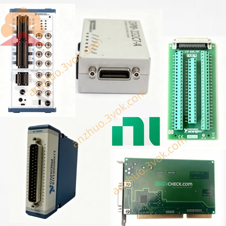
NI PXIe-8830MC PXImc Multi-Core Coprocessing Module
Description
Product Introduction
The NI PXIe-8830MC is a 3U single-slot PXIe multi-computing coprocessing module. It is designed based on the PXImc architecture and is equipped with a high-performance quad-core processor and runs the LabVIEW real-time operating system. This module can be installed in any external slot of the PXIe chassis and acts as a coprocessor to share the computing load of the system's main controller. It utilizes the PCIe high-speed link to achieve data communication between multiple nodes and is suitable for scenarios with high-load real-time computing, large-scale data processing, and complex closed-loop control that have strict requirements for computing power and real-time performance.
Model Interpretation
PXIe represents that the module uses the PXI Express bus and follows the industry-standard 3U single-slot mechanical standard, and is compatible with various standard PXIe chassis. 8830 belongs to the NI embedded computing module series number, and MC stands for multi-computing architecture. This model is a coprocessing unit and not the system main controller. It is mainly used to build distributed parallel computing nodes and expand the computing power of the entire system. Technical Specifications
Core hardware
The module is equipped with an Intel quad-core eight-thread processor with a base frequency of 2.4 gigahertz. It comes with 4 gigabytes of DDR3 memory, which can be expanded up to 8 gigabytes. The onboard storage medium is used for deploying the operating system and applications. The module adopts the PXIe Gen2 x8 bus, with a single-direction continuous transmission bandwidth of up to 2.7 gigabytes per second. The overall transmission delay between modules is approximately 5 microseconds.
Electrical and environmental parameters
The entire unit has a standard 3U size and typical operating power consumption of 25 watts. It is powered uniformly by the chassis backplane bus. The normal operating temperature range is 0 degrees Celsius to 55 degrees Celsius. It has industrial-grade anti-interference capabilities and can operate continuously for a long time.
Interface and communication configuration
Chassis bus interface
Connected to the chassis backplane via the PXIe Gen2 bus, it utilizes non-transparent bridge technology to achieve high-speed data interaction between the module and the main controller, other coprocessing modules, and can also call the chassis clock and trigger resources to ensure the synchronous execution of multi-node tasks.
Front panel interface and indicators
The panel is equipped with two USB interfaces, one gigabit Ethernet interface, and an independent reset button. It also integrates multiple sets of status indicators, which are used to display the power operation status, storage read/write status, and custom working status, allowing for intuitive judgment of the module's operation.
Driver and software communication
The module is pre-installed with the LabVIEW real-time operating system and comes with dedicated PXImc drivers. It can be completed through NI-MAX for hardware identification, system configuration, and status monitoring, fully compatible with NI series software such as LabVIEW and TestStand, and supports programming and task scheduling using mainstream development languages.
Core functions
As a coprocessor, it shares the computing tasks of the main controller, effectively enhancing the overall computing power of the entire system and avoiding the excessive load on the main device, which affects the operational efficiency. Based on the PXImc architecture, it supports parallel networking of multiple modules of the same model, building a high-density parallel computing cluster. It has high deterministic real-time operation capabilities and can complete precise closed-loop control, real-time signal analysis, and other tasks. The external peripheral interfaces on the panel can be used for connecting debugging equipment, networking communication, facilitating on-site debugging and remote management. The data transmission delay between modules is low, and the bandwidth is sufficient, meeting the requirements for high-speed data flow sharing and interaction. Applicable scenarios
In the field of radio frequency and wireless communication testing, we complete the decoding of massive radio frequency data, real-time spectrum analysis, and complex signal processing. In the automated testing platform, we are responsible for multi-channel parallel testing operations and complex test sequence scheduling, thereby improving testing efficiency. In industrial real-time control scenarios, we achieve high-precision motion control, equipment status collection, and logical operations. In the research experiments and simulation domain, we build parallel computing clusters and run complex algorithms and real-time simulation models. In large-scale distributed PXI systems, as independent computing nodes, we share the overall computing load.
User and Maintenance Instructions Instruction Manual
After the equipment is powered off, insert it into the peripheral slot of the PXIe chassis, tighten the fixing screws, and confirm that the connection is secure before reconnecting the power. Install the corresponding drivers and software tools in the main controller of the system, identify the coprocessing module through the software and complete the parameter configuration. Divide the computing tasks according to actual needs, deploy the corresponding programs to this module for execution. When connecting the device through an external interface, ensure that the cables are securely connected, and avoid touching the interface and buttons during operation. When networking multiple modules, unify the system clock and communication parameters to ensure data synchronization between nodes.
Maintenance Instructions
Regularly use a dry soft cloth to wipe the module casing, interface, and indicator light area, clean the surface dust, and strictly prohibit contact with liquids. Observe the status of the indicator lights daily, and determine whether the operation is normal based on the light effect. In case of any abnormalities, promptly check the power supply, cooling, and software configuration. During long-term continuous operation, regularly check the overall cooling environment of the chassis to prevent excessive temperature due to dust accumulation. When the equipment is idle for a long time, place it in a dry environment ranging from minus twenty degrees Celsius to sixty degrees Celsius, with a relative humidity of less than 60%, and take anti-static protection measures. When the system operation is sluggish or there are computing abnormalities, check the memory usage and program allocation, and re-deploy the system and applications if necessary.
Get a Quote