
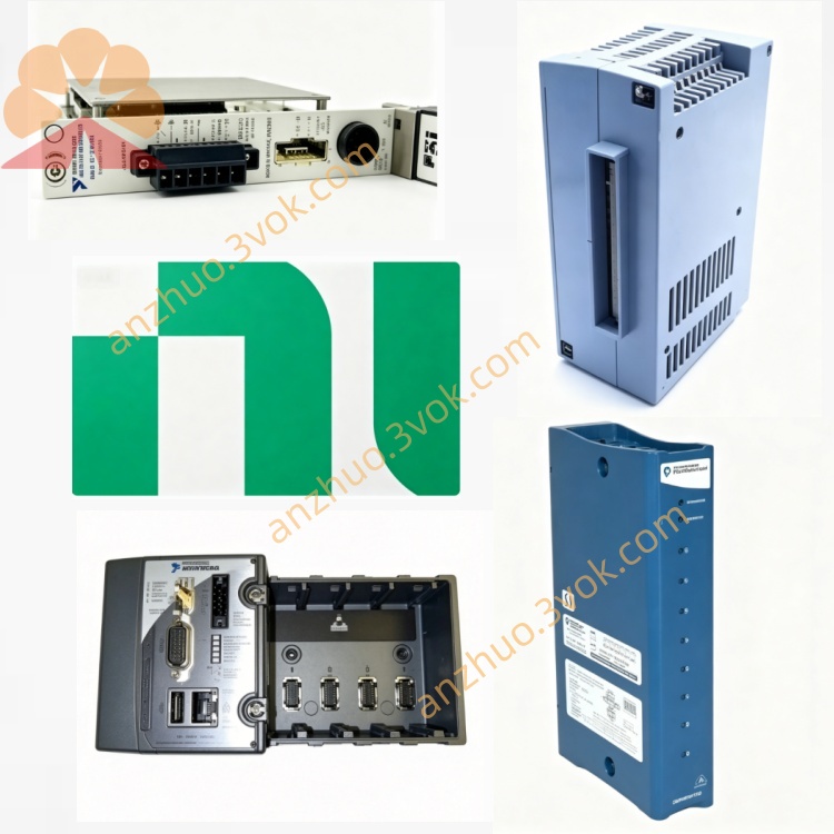
NI PXIe-6612 4-Channel Counter/Timer Module
Description
PXIe-6612 Product Introduction
PXIe-6612 is a 3U single-slot PXIe counter/timer module launched by National Instruments (NI). Model number is 782352-01. It integrates 8 32-bit counters/timers and 40 TTL/CMOS compatible bidirectional digital I/O. Based on the NI-STC3 timing chip, it focuses on high-frequency counting, precise timing measurement, and pulse generation. It is suitable for industrial control, embedded testing, and motion control scenarios.
Model Interpretation
PXIe: PXI Express bus, 3U single-slot specification
6612: NI X series timing/digital I/O module code, the core is 8 channels of counters + 40 DIO, 80 MHz high frequency, DMA high-speed transmission
782352-01: Standard model, no other suffix variants Technical Specifications
Core parameters of the counter/timer
Number of channels: 8 independent 32-bit counters/timers
Clock frequency: Internal maximum 100 MHz, external input maximum 80 MHz
Measurement modes: Event counting, period/frequency, pulse width, half cycle, bilateral edge interval, encoder position
Counting rate: No pre-divider 25 MHz, 2x pre-divider 50 MHz, 8x pre-divider 80 MHz
Data transmission: Supports 3 channels of simultaneous high-speed DMA, each channel has an independent DMA controller
Digital I/O characteristics
Number of channels: 40 bidirectional digital I/O
Logic levels: 5 V TTL/CMOS, high level ≥ 2.0 V, low level ≤ 0.8 V
Input characteristics: With digital de-joystick filter, software-configurable decoupling time
Output drive: Sinking/Driving current typical 4 mA, maximum 8 mA
General specifications
Size: 3U single slot (21.6×2.0×13.0 cm)
Operating temperature: 0 °C ~ 55 °C
Power supply: +5 V, typical power consumption 12 W
Protection: Overvoltage/overcurrent protection, ESD protection
Interface and communication configuration
Host bus interface
PXIe Gen1 ×1, plug-and-play, supports DMA
Backplane resources: PXI_CLK10, PXI trigger bus, RTSI, used for multi-module synchronization
Driver: NI-DAQmx (compatible with IVI), supports LabVIEW, C/C++, Python, TestStand
Front panel interface
1×68-pin VHDCI: includes 40 digital I/O, 8 counter input/output, PFI trigger lines
PFI channels: 8 dedicated counter sources (PFI11/15/19/23/27/31/35/39), the rest are general trigger I/O
No SMA interface, clock and trigger are distributed through VHDCI or backplane
Core functions
8 independent precise counting/timing: 32-bit resolution, maximum 80 MHz, supports multi-mode timing measurement
40 high-speed digital I/O: 5 V TTL/CMOS, bidirectional configurable, with decoupling filter, suitable for industrial signal interaction
Encoder position measurement: supports A/B phase quadrature encoding, maximum 20 MHz, real-time position tracking
Flexible pulse generation: can generate single pulse, pulse string, PWM, frequency/duty ratio software adjustable
High-speed DMA data transmission: 3 channels of simultaneous DMA, realizes continuous counting without loss and I/O flow
Multi-module synchronization: through PXI trigger bus/RTSI, builds multi-module synchronous measurement system Applicable scenarios
Industrial control and monitoring: Pulse counting on production line, rotational speed measurement, flow/frequency monitoring
Motion control: Servo/stepper motor encoder feedback, position closed-loop control
Embedded system testing: PWM signal generation and measurement, digital pulse protocol verification
Electronic manufacturing: Component counting, timing parameter testing, relay/switch life testing
Research and teaching: Precise timing experiments, pulse signal analysis, digital logic teaching platform
User and maintenance instructions Instruction Manual
Installation: Insert the standard 3U PXIe chassis and secure the screws; the length of the VHDCI cable should be ≤ 1 meter to avoid strong electromagnetic interference.
Configuration: Identify the hardware through NI-MAX, configure the counter mode, digital I/O direction and decoupling parameters using NI-DAQmx.
Synchronization: When synchronizing multiple modules, use the backplane PXI_CLK100 or an external reference clock, and calibrate the trigger phase.
Operation: Power on and preheat for 15 minutes before running; avoid hot swapping to prevent electrostatic damage.
Maintenance instructions
Cleaning: Regularly wipe the panel and connectors with a dry soft cloth to prevent dust and moisture.
Calibration: Calibrate the counter accuracy, timing error and I/O level every 2 years.
Storage: Store in an environment of −20 °C ~ 60 °C with humidity < 60% for long-term use, and use anti-static packaging.
Fault troubleshooting: When encountering an anomaly, first check the wiring, power supply and driver; for counter anomalies, check the clock source and trigger; for I/O anomalies, check if the load is short-circuited.
Get a Quote