
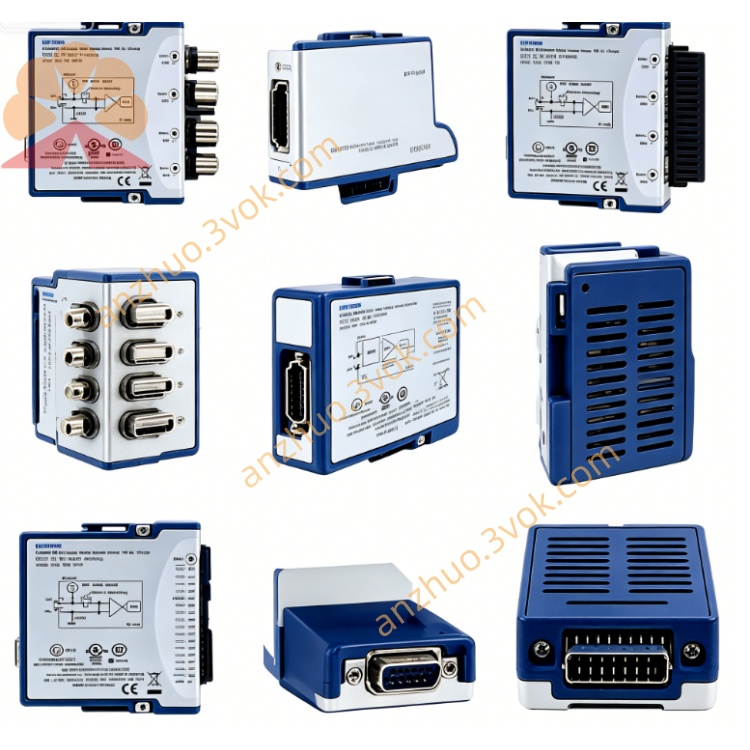
NI PXIe-6571 Digital Pattern Test Instrument
Description
PXIe-6571 Product Introduction
PXIe-6571 is a 3U single-slot PXIe high-performance digital pattern instrument launched by National Instruments (NI). It comes in two versions: 8 channels (786320-02) and 32 channels (786320-01), designed specifically for the verification, characteristic analysis, and mass production testing of semiconductor chips. It integrates high-speed digital excitation / acquisition, per-pin parameter measurement (PPMU), and large-capacity vector storage. It is a digital test module on the PXI platform that matches the performance of ATE (Automatic Test Equipment) from NI.
Model Interpretation
PXIe: PXI Express bus, Gen2 ×4, 3U single-slot standard specification
6571: NI's high-performance digital pattern instrument series code, the core features are 100 MHz vector rate, PPMU integration, and multi-site testing
Suffix: 786320-01 (32 channels), 786320-02 (8 channels) Technical Specifications
Channel and Electrical Characteristics
Channel Configuration: 8-channel or 32-channel single-ended bidirectional I/O
Digital Level: -2 V ~ +6 V, compatible with mainstream logic levels
PPMU Capability: -2 V ~ +7 V forced voltage, ±32 mA pull/hold current, supports precise DC parameter measurement by NI
Edge Resolution: 39.0625 ps, 31 timing sets, meets fine timing tolerance test by NI
Timing and Performance
Maximum Vector Rate: 100 MHz (100 MVector/s), Peak Data Rate 200 Mb/s by NI
Clock Generation: Maximum 160 MHz, supports multi-module synchronous clock distribution by NI
Vector Memory: 128 Mbit / channel, supports complex long test sequences
Multi-site Testing: Single module supports up to 8 parallel test sites
General Specifications
Size: 3U single slot (21.6×2.0×13.0 cm)
Operating Temperature: 0 °C ~ 40 °C
Heat Dissipation Requirements: ≥58 W / slot for 8 channels; ≥82 W / slot for 32 channels
Protection: Overvoltage / Overcurrent / Short-circuit protection, DUT ground sensing (DGS)
Interface and Communication Configuration
Host Bus Interface
PXIe Gen2 ×4, plug-and-play, supports DMA high-speed transmission
Backplane Resources: PXI_CLK100, PXI trigger bus, RTSI, used for multi-module / multi-box synchronous
Maximum Throughput: meets real-time data throughput under 100 MHz vector rate
Front Panel Interface
1×68-pin VHDCI: includes all digital I/O, PPUM forced / induced, DUT ground sensing (DGS) and calibration signals
SMA Interface: CLK IN (external reference clock), CLK OUT (clock output), PFI (programmable trigger)
Auxiliary I/O: for external triggering, fault injection and calibration control
Driver and Software Communication
Driver: NI-HSDIO, compatible with IVI standard
Configuration Tool: NI-MAX (hardware identification, self-check, calibration)
Development Environment: LabVIEW, C/C++, Python, TestStand
Special Software: Digital Pattern Editor (pin mapping, levels, timing, pattern editing) by NI
Core Functions
High-speed Digital Pattern Generation and Acquisition: 100 MHz vector rate, supports NR/RL/RH/SBC various drive formats, real-time hardware comparison and error detection by NI
Per-pin DC Parameter Testing (PPMU): measures VIH/VIL/VOH/VOL, leakage current, drive current, four-quadrant precise measurement
Ultra-high Timing Precision: 39 ps edge resolution, 31 timing sets, meets high-speed interface timing tolerance test by NI
Large-capacity Storage and Complex Sequences: 128 Mbit / channel, supports flow control, subroutines, loops and multi-site independent patterns
Multi-module Synchronization and Large-scale Testing: Backplane clock / trigger synchronization, scalable to 512 channels, builds parallel ATE system
Debugging and Analysis Tools: built-in Shmoo graph, digital oscilloscope, history RAM viewer, pin status monitoring by NI Applicable scenarios
Semiconductor / IC Testing: Functional, timing and DC parameter verification for logic chips, MCUs, FPGAs, SoCs, and power management chips (PMICs) using NI
High-speed Interface Testing: Protocol and signal integrity testing for digital interfaces such as SPI, I²C, UART, LVCMOS, etc.
Mixed Signal Testing: DC parameter measurement for digital excitation + analog / power pins, testing of digital control parts of RF chips using NI
Large-scale Parallel Production Testing: Synchronous multi-module testing, 8-site parallel testing to enhance production testing efficiency
Research and Reliability Verification: Long-term stability and fault injection testing for high-reliability digital systems in aerospace and automotive electronics
User and Maintenance Instructions Instruction Manual
Installation: 8-channel insertion for ≥58W cooling slots, 32-channel insertion for ≥82W cooling slots (such as PXIe-1095), with fixed screws
Wiring: High-speed signal cables length ≤ 1 meter, VHDCI connects digital I/O with PPMU, SMA uses 50Ω coaxial line
Configuration: Set pin mapping, levels, timing, patterns through Digital Pattern Editor; Enable PPMU measurement and hardware comparison
Operation: Self-check after 30 minutes of power-on preheating; Avoid hot-plugging; Calibrate reference clock before multi-module testing
Maintenance instructions
Cleaning: Regularly wipe the panel and connectors with a dry soft cloth to prevent dust and moisture, and avoid contact with liquids
Calibration: Calibrate the level, current, timing and DC measurement accuracy once a year
Storage: Store in an environment of -20 °C ~ 60 °C with humidity < 60%, in an anti-static package
Troubleshooting: When there is an anomaly, first check the wiring, power supply and software configuration; for timing anomalies, check the cables and grounding; for output / measurement anomalies, check if the load is short-circuited or overloaded
Get a Quote