
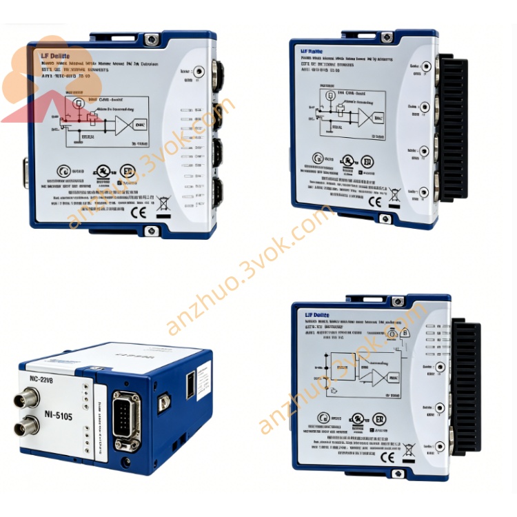
NI PXIe-6556 200MHz Digital Waveform Instrument with PPMU
Description
PXIe-6556 Product Introduction
PXIe-6556 is a 3U single-slot PXIe high-speed digital waveform generator/analyser developed by National Instruments (NI). It integrates 24 bidirectional digital I/O and per-pin parameter measurement unit (PPMU), enabling simultaneous high-speed digital excitation/collecting and precise DC parameter testing at the same pin. It is a high-performance integrated module for semiconductor, embedded, and mixed-signal testing.
Model Interpretation
PXIe: PXI Express bus, Gen1 ×4, 3U single-slot standard specification
6556: NI's high-performance digital test module series code, the core feature is 24 channels, 200 MHz, with PPMU, large memory
Model suffix: 781949-01 (8 Mbit / channel), 781949-02 (64 Mbit / channel) Technical Specifications
Channel and Electrical Characteristics
24 single-ended bidirectional channels, each channel with independent input/output/high-impedance
Programmable levels: -2 V ~ +7 V, compatible with 1.2/1.5/1.8/2.5/3.3/5 V mainstream logic
Each channel integrates PPMU, ±35 mA sinking / sourcing current, DC voltage/current measurement accuracy 1%
Remote sensing (Remote Sense): 28 channels, eliminating cable voltage drop error NI
Timing and Performance
Maximum clock: 200 MHz (SDR), data rate 200 Mbit/s
Channel-to-channel jitter: <1 ns, pin-level timing resolution 30 ps
Hardware real-time bit comparison, bit error counting, error halt
Memory: 8 Mbit / channel (standard version) or 64 Mbit / channel (high-end version)
General Specifications
Size: 3U single slot (21.6×2.0×13.0 cm)
Operating temperature: 0 °C ~ 55 °C
Protection: Overvoltage / overcurrent / short circuit protection, electrostatic discharge design
Interface and Communication Configuration
Host bus interface
PXIe Gen1 ×4, plug-and-play, supports DMA
Throughput: Input 660 MB/s, output 400 MB/s
Backplane resources: PXI_CLK100, PXI trigger bus, RTSI, for multi-module synchronization NI
Front panel interface
2×68-pin VHDCI: 1 digital data and control (DDC), including 24-channel I/O, STROBE, trigger; 1 remote sensing (Remote Sense), for high-precision DC measurement NI
3×SMA: CLK IN (5–100 MHz external clock), CLK OUT (reference clock output), PFI 0 (programmable trigger I/O) NI
1×Combicon: auxiliary I/O, for external forcing / sensing and analog calibration NI
PFI channels: 4 channels with PPMU (PFI1/2/4/5), 10 channels general (PFI0/3/24~31) docs-be.ni.com
Drivers and Software Communication
Driver: NI-HSDIO (compatible with IVI)
Configuration tool: NI-MAX (hardware identification, self-check, calibration)
Development environment: LabVIEW, C/C++, Python, TestStand
API: waveform generation / acquisition, hardware comparison, PPMU measurement, timing configuration
Core Functions
24-channel high-speed bidirectional test: 200 MHz, multi-level, real-time hardware comparison, supports bit error rate and protocol verification
Per-pin DC parameter test (PPMU): measurement of VIH/VIL/VOH/VOL, leakage current, driving current, four-quadrant precise measurement
Remote sensing high-precision measurement: eliminating the influence of cable resistance, improving DC test accuracy NI
Advanced timing and synchronization: timing self-correction, hardware timing measurement, multi-module / multi-rack synchronization (jitter < 1 ns)
Active load and external SMU connection: configurable as digital line load, supports external precision source table to enhance measurement accuracy
Large memory and script programming: 8/64 Mbit / channel, supports complex test sequences, loops and flow processing NI Applicable scenarios
Semiconductor / IC Testing: Function, timing and DC parameter verification of logic chips, MCUs, FPGAs, interface chips (I²C/SPI/UART/LVCMOS)
Embedded System Testing: Digital I/O timing margin, fault injection, bit error rate testing
Mixed Signal Testing: DC parameter measurement of digital excitation + power / GPIO pins
Large-scale Parallel Production Testing: Synchronization of multiple modules to enhance testing efficiency
Aerospace / Research: Verification of high-reliability digital systems and precise parameter testing
User and Maintenance Instructions Instruction Manual
Installation: Insert into a standard 3U PXIe chassis and secure the screws; the length of the high-speed signal cable should be ≤ 1 meter, and the SMA port should use a 50Ω coaxial line NI
Configuration: Set the channel direction, level, clock, and trigger through NI-MAX; load the test pattern, compare the rules with PPMU parameters; calibrate the reference clock before multi-device synchronization NI
Operation: Power on for self-check first, then run the test; avoid hot swapping, and pay attention to heat dissipation when operating at high temperature NI
Maintenance instructions
Cleaning: Regularly wipe the panel and connectors with a dry soft cloth to prevent dust and moisture
Calibration: Calibrate the level, current, timing, and DC measurement accuracy once every 2 years
Storage: Store in an environment of −20 °C ~ 60 °C with humidity < 60%, in an anti-static package
Troubleshooting: When there is an anomaly, first check the wiring, power supply, and software configuration; for timing anomalies, check the cable and grounding; for output / measurement anomalies, check if the load is short-circuited or overloaded NI
Get a Quote