
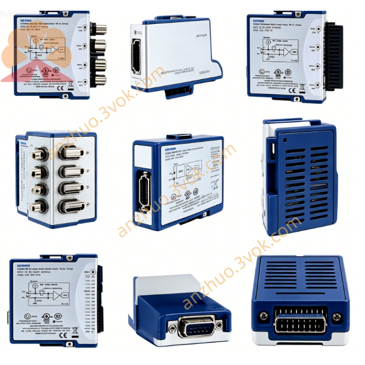
NI PXIe-5162 1.5GHz 5GS/s 10-bit PXIe Modular Oscilloscope Digitizer
The PXIe-5162 is a high-performance oscilloscope and digitizer built in a 3U single-slot PXIe form factor. It features 10-bit resolution, up to 1.5 GHz bandwidth and a maximum real-time sampling rate of 5 GS/s. Available in 2-channel and 4-channel versions, this module is designed for capturing wideband and high-speed signals. Equipped with large onboard memory and flexible front-end settings, it delivers reliable performance for high-frequency measurement, time-domain analysis and multi-instrument synchronized test systems.
Description
Model Nomenclature
PXIe represents the PXI Express high-speed modular instrumentation bus. The number 51 stands for the series of PXI oscilloscopes and digitizers. 5162 refers to a 10-bit module with 1.5 GHz bandwidth and maximum 5 GS/s sampling rate.
Technical Specifications
This module comes as a 3U single-slot PXIe device with two or four fully independent analog input channels. It adopts 10-bit vertical resolution. The analog bandwidth reaches 1.5 GHz under 50 ohm input impedance, and 300 megahertz under 1 megaohm input impedance. The sampling rate varies with active channels, delivering 5 GS/s for a single channel, 2.5 GS/s for two channels and 1.25 GS/s for four channels.
Users can select either 50 ohm or 1 megaohm input impedance via software. Multiple full-scale voltage ranges are provided for different measurement demands. The onboard memory depth is 2 gigabytes per channel to support long-duration continuous acquisition. The typical spurious-free dynamic range is above 50 dBc, and the typical rise time is approximately 1.4 nanoseconds under 50 ohm impedance. It supports software-selectable built-in filters and comprehensive trigger functions.
The operating temperature ranges from 0 degrees Celsius to 55 degrees Celsius, while the storage temperature ranges from minus 40 degrees Celsius to 70 degrees Celsius. All analog and trigger signals connect through front-panel BNC connectors.
Interface and Communication Configuration
The module uses PXIe Gen1 bus and supports plug-and-play operation on Windows operating systems. It works with NI-Scope and NI-DAQmx drivers. Supported development software includes NI-MAX for device configuration and diagnosis, as well as LabVIEW, C, C++, Python and .NET for custom programming and automated control.
It fully supports PXI trigger lines, PXIe star trigger and NI-TClk synchronization technology, enabling precise timing alignment with other PXIe instruments. External clock input and output are also available. It adopts direct memory access for high-speed data streaming, and supports multi-record acquisition for capturing batches of repetitive waveforms.
Core Features
It provides ultra-wide bandwidth and high sampling speed, which can accurately capture high-frequency RF signals and high-speed digital waveforms. The switchable input impedance adapts to both high-frequency matched circuits and general high-impedance measurement scenarios. With 2 gigabytes deep onboard memory, it achieves long-time waveform recording without frequent data transmission to the host.
Rich trigger modes including edge, pulse, window and pattern trigger help stably capture abnormal and complex waveforms. AC and DC coupling options and adjustable voltage ranges enhance measurement flexibility. High-precision multi-module synchronization makes it suitable for large-scale integrated test systems. The optional CableSense function can detect faults on signal cables and connections.
Application Scenarios
It is widely used for radar signal acquisition and performance verification in aerospace and defense fields. It conducts testing and timing analysis for high-speed digital interfaces such as high-speed Ethernet and memory buses. It performs characterization tests on high-speed I/O, clock signals and power rails of semiconductors and integrated circuits.
The module is applied to validation of high-frequency signals from automotive electronic control units and sensors. It also serves for baseband and intermediate frequency signal analysis in wireless communication equipment research and production test.
Usage and Maintenance Instructions
Installation and Configuration
Insert the module into a vacant 3U slot of the PXIe chassis and fasten the front panel latch. Connect signal cables to the front-panel BNC connectors according to application requirements. Use 50 ohm matching for high-frequency signals. Power on the chassis, and the system will automatically identify the module. Open NI-MAX to set input impedance, voltage range, sampling parameters and trigger conditions before starting measurement tasks.
Operation
Allow a 15-minute warm-up period before conducting high-precision measurements. Always keep the input signal within the rated voltage range to avoid damage to the front-end circuit. Select appropriate filters and trigger settings based on signal characteristics. Enable multi-record acquisition mode when capturing periodic burst signals.
Daily Maintenance
Keep the module, cables and connectors clean, dry and well ventilated during use. Do not apply excessive force when installing and removing BNC connectors to prevent pin damage. Inspect cables and connections regularly for aging or poor contact. Follow the official guide to perform calibration every two years to maintain long-term measurement accuracy. When not in use, disconnect all cables and store the module in an electrostatic protected environment.
Get a Quote