140XTS00100
Description
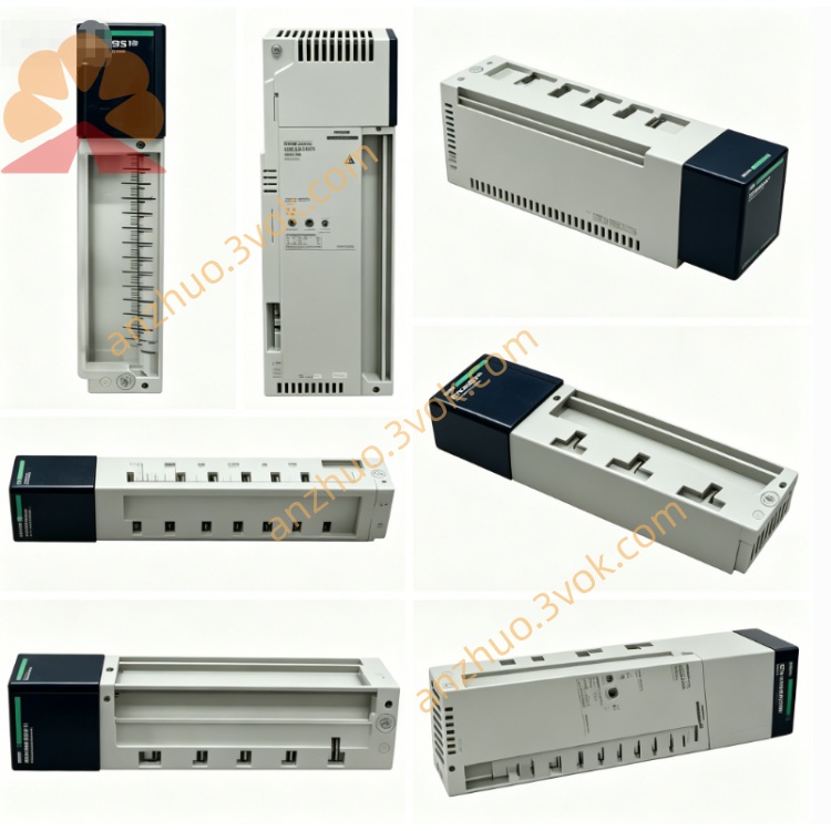
1. General Description
2. Part Number and Identification
Model: 140XTS00100
Product line: Modicon Quantum
Type: I/O terminal block, 40 points, screw connection
Function: Field wiring termination for Quantum I/O modules
Net weight: 0.17 kg (0.38 lb)
Housing material: UL94 V‑0 flame‑retardant thermoplastic
Country of origin: France
Approvals: CE, UL, cUL, RoHS compliant
IP rating: IP20 (finger‑safe, no protection against water)施耐德电气
3. Electrical Characteristics
Number of terminals: 40 (2 rows × 20)
Connection type: Screw terminal (M3 screws, captive)
Conductor size: 0.2–2.5 mm² (24–14 AWG), single or stranded
Rated voltage: 300 VAC / 450 VDC
Rated current: 10 A per terminal (continuous)
Contact resistance: < 5 mΩ (initial)
Isolation: Galvanic isolation between adjacent terminals
Torque specification: 0.5–0.6 N·m (4.4–5.3 lb‑in)
4. Mechanical Specifications
Dimensions (H × W × D): 130 mm × 85 mm × 25 mm (5.12 in × 3.35 in × 0.98 in)
Mounting: Direct plug‑in to the front of compatible Quantum I/O modules
Termination: Front‑facing screw terminals for easy wiring access
Labeling: Pre‑numbered terminals (1–40) for quick identification
Locking: Integrated snap‑lock mechanism for secure module attachment
Removal: Tool‑free release tab
5. Environmental Ratings
Operating temperature: 0 °C to +60 °C, non‑condensing
Storage temperature: −25 °C to +85 °C
Humidity: 5 % to 95 % RH, non‑condensing
Maximum altitude: 2,000 m (6,562 ft) above sea level
Shock/vibration: Industrial grade (IEC 60068‑2‑6)
6. Compatibility
PLC series: Modicon Quantum
Discrete input modules: 140DAI54000, 140DAI74000
Discrete output modules: 140DAO84000, 140DAO85000
Analog input modules: 140AVI03000, 140ATI03000, 140ACI03000
Analog output modules: 140AVO02000, 140ACO02000, 140AMM09000
Not compatible with Quantum X80 or M340 series modules
7. Installation and Wiring
1. Module Preparation
Ensure the target I/O module is installed in the Quantum rack and powered off.
2. Terminal Block Attachment
Align the 140XTS00100 with the front connector of the I/O module.
Push firmly until the snap‑lock engages (audible click).
3. Field Wiring
Strip wire insulation to 6–7 mm (0.24–0.28 in).
Loosen the terminal screw using a Phillips screwdriver.
Insert the wire into the terminal clamp.
Tighten the screw to 0.5–0.6 N·m torque.
Label wires per site standards for traceability.
4. Removal
Power off the I/O module.
Press the release tab and pull the terminal block straight out.
8. Maintenance
Inspection: Check terminal tightness and wire integrity quarterly.
Cleaning: Wipe the front panel with a dry cloth; avoid solvents.
Torque check: Verify screw torque annually (0.5–0.6 N·m).
Storage: Keep in a dry, clean environment when not in use.
9. Safety Instructions
Use only with compatible Modicon Quantum I/O modules.
Ensure the I/O module is powered off during installation/removal.
Do not exceed rated voltage/current limits.
Maintain IP20 integrity; do not modify the housing.
For indoor use only; not for direct exposure to water or dust.
10. Warranty
12‑month manufacturer warranty against defects in materials and workmanship.
Get a Quote