170DNT11000
Description
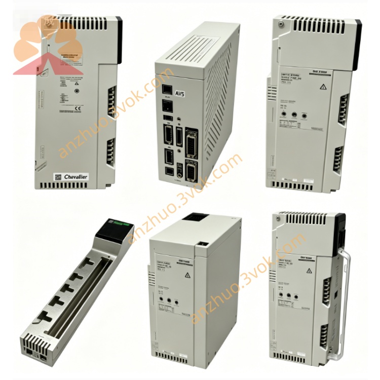
1. General Description
2. Product Identification
Model Number: 170DNT11000
Series: Modicon Momentum
Type: PROFIBUS DP Communication Adapter
Protocol: PROFIBUS DP (Master/Slave)
Connector: 1 × 9‑pin SUB‑D
Transmission Medium: Shielded twisted pair
Topologies: Multidrop, Ring
Addressing: Two rotary switches (1–99)
LED Indicator: 1 × green LED (BF: Bus Fault)
Dimensions (W × D × H): 125 × 45 × 100 mm
Weight: 0.07 kg (0.19 lb)
Protection Class: IP20
Certifications: CE, UL, cUL, CSA, RoHS
3. Communication Specifications
Data Rates: 9.6 kbps, 19.2 kbps, 93.75 kbps, 187.5 kbps, 500 kbps, 1.5 Mbps, 3 Mbps, 6 Mbps, 12 Mbps
Nodes per Segment: 0 to 126 devices
Max. Cable Length: 1200 m (depending on baud rate)
Data Integrity: CRC‑16 checksum
Isolation: Galvanic isolation between backplane and field network
Fail State: Fail‑safe (outputs set to predefined state on fault)
4. Electrical Specifications
Power Supply: 24 VDC (from Momentum I/O base backplane)
Current Consumption: ≤ 100 mA @ 24 VDC
Voltage Range: 19.2 VDC to 28.8 VDC (±20%)
Surge Protection: 600 W
Overcurrent Protection: 1.5 A
EMC Compliance:
Electrostatic Discharge (ESD): ±4 kV contact, ±8 kV air (IEC 61000‑6‑2/4)
5. Environmental Ratings
Operating Temperature: 0 °C to +60 °C (non‑condensing)
Storage Temperature: −40 °C to +85 °C
Relative Humidity: 5% to 95% (non‑condensing)
Vibration: IEC 60068‑2‑6 (1 g, 10–150 Hz)
Shock: IEC 60068‑2‑27 (15 g, 11 ms)
Altitude: Up to 5000 m (derated above 2000 m)
6. Key Features
Master/Slave Support: Flexible operation in PROFIBUS DP networks.
High‑Speed Communication: Up to 12 Mbps for real‑time control.
Long‑Distance Capability: Up to 1200 m per segment.
Dual Topologies: Multidrop or ring for network redundancy.
Easy Configuration: Rotary switches for station address (1–99).
LED Diagnostics: BF LED for quick bus fault identification.
Compact Design: Fits standard control cabinets (IP20).
Backplane‑Powered: No external power supply needed.
7. Compatibility
I/O Bases: All Modicon Momentum I/O bases (170XBP series).
Controllers: Modicon Quantum, Premium, M340, Momentum CPUs.
Software: Unity Pro, SoMachine (for configuration and programming).
Cables: PROFIBUS DP‑compliant shielded twisted pair.
Termination: Active or passive PROFIBUS terminators (required at segment ends).
8. Installation & Operation
Power Off: Disconnect all system power before installation.
Mounting:
Insert the adapter into the Momentum I/O base’s communication slot.
Secure with the integrated latch.
Address Setting:
Use the two rotary switches on the front to set the PROFIBUS station address (1–99).
Wiring:
Connect the PROFIBUS cable to the 9‑pin SUB‑D connector.
Ensure proper shielding and termination at both ends of the segment.
Power On: Restore system power.
LED Status:
BF (Green): Off = Normal; Flashing/Solid = Bus fault (check wiring, termination, or master configuration).
9. Configuration
Use Unity Pro or SoMachine software to configure the adapter as a PROFIBUS DP master or slave.
Set baud rate, station address, and I/O data mapping in the software.
Download the configuration to the PLC and adapter.
10. Maintenance
Inspection: Every 6 months, check connections, LED operation, and cable integrity.
Cleaning: Use a dry cloth only; avoid moisture, dust, and chemicals.
Environment: Keep away from corrosive gases and condensation.
11. Safety Notes
Qualified Personnel: Installation and maintenance must be performed by certified electricians.
Voltage Limits: Do not exceed 30 VDC on the PROFIBUS interface.
Isolation: Do not modify internal isolation barriers.
Disposal: Dispose of the module in accordance with local electronic waste regulations.
12. Troubleshooting
BF LED Flashing: Check PROFIBUS cable wiring, termination, or master/slave address conflicts.
No Communication: Verify baud rate matching, station address, and power supply.
Data Errors: Check cable shielding, grounding, or EMI sources nearby.
Get a Quote