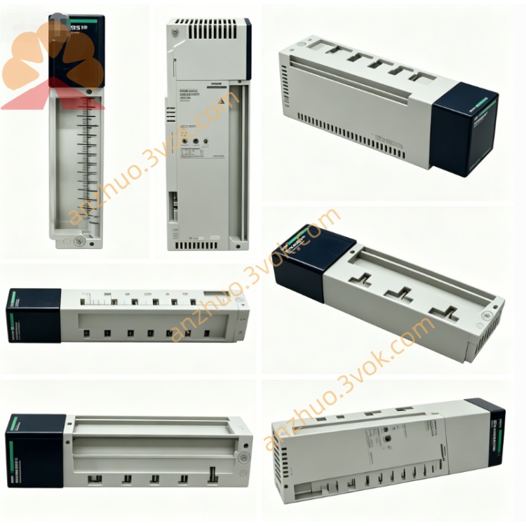
170BSM01600
Description
1. General Description
2. Product Identification
Model Number: 170BSM01600
Series: Modicon Momentum
Type: Discrete input simulator (test module)
Channels: 16 × discrete input simulation (24 VDC)
Dimensions (W × D × H): 155 × 45 × 100 mm
Weight: 0.45 kg
Protection Class: IP20
Certifications: CE, UL, cUL, CSA, RoHS
LED Indicators: 7 LEDs (power + 6 status)
Mounting: DIN rail or direct to Momentum backplane
3. Electrical Specifications
Simulation Inputs (16 Channels)
Signal Type: 24 VDC discrete, positive logic
Simulation Levels:
Logic 1 (ON): 24 VDC ±10%
Logic 0 (OFF): 0 VDC
Output Current (per channel): 5–10 mA (sinking)
Response Time: < 1 ms (ON/OFF)
Isolation: Channel-to-channel non‑isolated; backplane isolated
Power
Supply Voltage: 24 VDC ±10% (from backplane or external)
Current Consumption: ≤ 100 mA @ 24 VDC
Power Dissipation: ≤ 2.4 W
4. Environmental Ratings
Operating Temperature: −20 °C to +55 °C, non‑condensing
Storage Temperature: −40 °C to +75 °C
Relative Humidity: 5% to 95%, non‑condensing
Vibration: IEC 60068‑2‑6 (1 g, 10–150 Hz)
Shock: IEC 60068‑2‑27 (15 g, 11 ms)
Altitude: Up to 3000 m
EMC: IEC 61000‑6‑2 / 61000‑6‑4 (industrial)
5. Key Features
16‑Channel Simulation: Emulates 24 VDC sensor inputs for full I/O testing.
No Field Wiring: Test PLC logic, interlocks, and sequences offline.
LED Status: Power + 6 status LEDs for quick visual check.
Dual Mounting: DIN rail or Momentum backplane for flexibility.
Compact & Light: Easy to carry for on‑site commissioning.
Low Power: Minimal load on system power supply.
6. Compatibility
Backplane: Modicon Momentum I/O rack (170XBP series)
Controllers: Quantum, Premium, M340, Momentum
Software: Unity Pro, SoMachine, Modbus RTU/TCP
Wiring: 18–24 AWG, torque 0.4–0.5 N·m
7. Applications
Factory Acceptance Testing (FAT): Simulate all sensor inputs for PLC program validation.
Site Commissioning: Test I/O logic before field devices are installed.
Troubleshooting: Isolate PLC vs. field wiring issues.
Training: Teach PLC programming and I/O handling without physical sensors.
System Demo: Showcase automation sequences at trade shows or customer sites.
8. Installation & Operation
Power Off: Disconnect system power before installation.
Mounting:
Backplane: Snap onto Momentum I/O rack.
DIN Rail: Mount in cabinet, connect 24 VDC power.
Wiring: Connect simulator outputs to PLC input terminals (24 VDC common).
Operation:
Use switches (internal or external) to set channels ON/OFF.
Verify PLC input status via software or LED indicators.
LEDs:
PWR: Green = 24 VDC OK
CH1–CH16: Status via grouped LEDs
9. Maintenance
Inspection: Check connections and LED operation every 6 months.
Cleaning: Use dry cloth; avoid moisture and chemicals.
Environment: Keep away from corrosive gases and condensation.
10. Safety Notes
Qualified Personnel: Only certified electricians may install/operate.
Voltage Limits: Do not exceed 30 VDC on inputs.
Isolation: Do not modify internal isolation barriers.
Disposal: Dispose per local e‑waste regulations.
Get a Quote