170FNT11000
Description
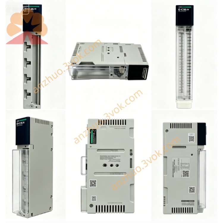
1. General Description
2. Product Identification
Model Number: 170FNT11000
Series: Modicon Momentum
Type: FIPIO Communication Adapter
Protocol: FIPIO (fieldbus)
Connector: 1 × 9‑pin SUB‑D (electrical)
Transmission Medium: Shielded twisted pair (STP)
Data Rate: 1 Mbps (fixed)
Station Address: 2 rotary switches (1–99)
LED Indicators: 2 LEDs (RUN, FLT)
Dimensions (W × D × H): 125 × 45 × 100 mm
Weight: 0.09 kg (0.19 lb)
Protection Class: IP20
Certifications: CE, UL, cUL, CSA, RoHS
3. Communication Specifications
Network Protocol: FIPIO (factory instrumentation protocol)
Data Rate: 1 Mbps (fixed, no software selection)
Topology: Multidrop (bus)
Nodes per Segment: Max 31 devices (without repeater)
Max Cable Length: 1,000 m (STP at 1 Mbps)
Data Integrity: CRC‑16 checksum
Isolation: Galvanic isolation between backplane and FIPIO network
Supported PLCs:
TSX Telecontroller 40 (v5.5+)
APRIL CPU5030 / CPU5130 (v2+)
4. Electrical Specifications
Power Supply: 24 VDC (from Momentum I/O base backplane)
Current Consumption: ≤ 120 mA @ 24 VDC
Voltage Range: 19.2 VDC to 28.8 VDC (±20%)
Surge Protection: 600 W
Overcurrent Protection: 1.5 A
EMC Compliance: IEC 61000‑6‑2/4 (industrial immunity)
5. Environmental Ratings
Operating Temperature: 0 °C to +60 °C (non‑condensing)
Storage Temperature: −40 °C to +85 °C
Relative Humidity: 5% to 95% (non‑condensing)
Vibration: IEC 60068‑2‑6 (1 g, 10–150 Hz)
Shock: IEC 60068‑2‑27 (15 g, 11 ms)
Altitude: Up to 5,000 m (derated above 2,000 m)
6. Key Features
FIPIO Protocol: Native support for FIPIO fieldbus (1 Mbps)
Backplane‑Powered: No external power supply needed
Rotary Addressing: Simple station address setup (1–99)
LED Diagnostics: RUN (green) and FLT (red) for status
Galvanic Isolation: Protects backplane from fieldbus faults
Compact Design: Fits standard Momentum I/O slots (IP20)
Industrial Grade: High immunity to EMI and harsh environments
7. Compatibility
I/O Bases: All Modicon Momentum 170XBP series bases
Controllers: TSX Telecontroller 40, APRIL CPU5030/5130
Configuration Software: XTEL V52/V6, Unity Pro (FIPIO configuration)
Cables: FIPIO‑compliant shielded twisted pair (STP)
Termination: Passive terminator (required at both ends of segment)
8. Installation & Operation
Power Off: Disconnect all system power before installation.
Mounting:
Insert adapter into Momentum I/O base’s communication slot.
Secure with integrated latch.
Address Setting:
Use two front rotary switches to set FIPIO station address (1–99).
Wiring:
Connect FIPIO STP cable to 9‑pin SUB‑D connector.
Ensure proper shielding and termination at segment ends.
Power On: Restore system power.
LED Status:
RUN (Green): On = Normal operation; Flashing = Initialization.
FLT (Red): On = Bus fault; Flashing = Configuration error.
9. Configuration
Use XTEL V52/V6 or Unity Pro to configure the adapter as a FIPIO slave.
Set station address (must match rotary switches) and I/O data mapping.
Download configuration to PLC and adapter.
10. Maintenance
Inspection: Every 6 months, check connections, LED status, and cable integrity.
Cleaning: Use dry cloth only; avoid moisture, dust, chemicals.
Environment: Keep away from corrosive gases and condensation.
11. Safety Notes
Qualified Personnel: Installation/maintenance by certified electricians only.
Voltage Limits: Do not exceed 30 VDC on FIPIO interface.
Isolation: Do not modify internal isolation barriers.
Disposal: Dispose of module per local electronic waste regulations.
12. Troubleshooting
FLT LED On: Check FIPIO cable wiring, termination, or address conflicts.
No Communication: Verify station address, PLC configuration, and backplane power.
Data Errors: Check cable shielding, grounding, or nearby EMI sources.
Get a Quote