140XSM01000
Description
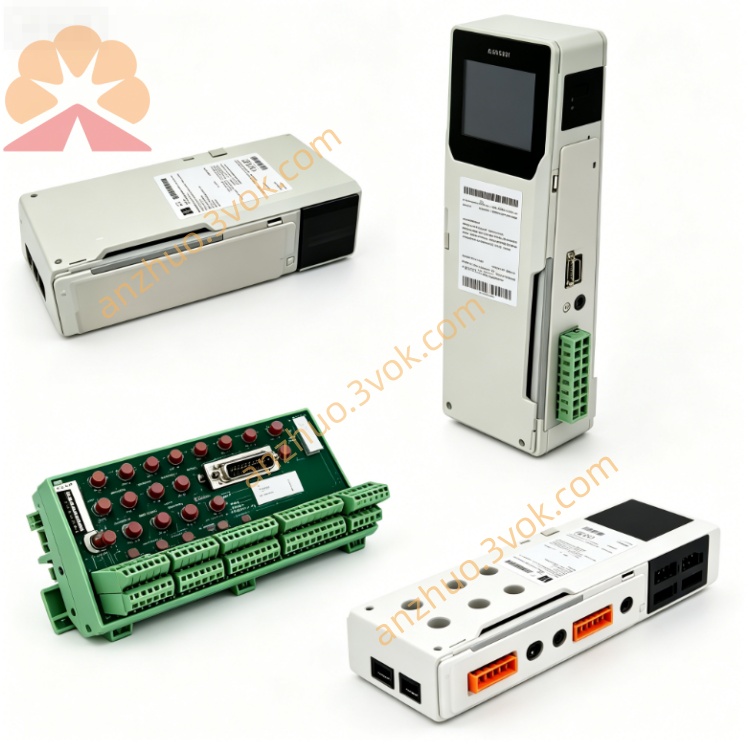
1. General Description
2. Part Number and Identification
Model: 140XSM01000
Product line: Modicon Quantum
Type: Analog I/O simulator, voltage/current
Function: Simulation of 1–5 VDC, 0–5 VDC, and 4–20 mA analog signals
Net weight: Approximately 0.57 kg (1.25 lb)
Housing material: UL94 V‑0 flame‑retardant plastic
Country of origin: France
Approvals: CE, UL, cUL, RoHS compliant
Compatible modules: 140AVI03000, 140AVO02000, 140ACO02000, 140ATI03000, 140ACI03000, 140AMM09000
3. Electrical Characteristics
Simulated Input Ranges
Voltage: 1–5 VDC (adjustable), 0–5 VDC (fixed)
Current: 4–20 mA (adjustable, two independent channels)
Adjustment Controls
Two 10‑turn precision potentiometers (for 4–20 mA / 1–5 VDC)
One 0–5 VDC digital voltmeter (on‑board display)
Internal Power Supply
Output: 24 VDC, 400 mA maximum (for powering external loops)
Source: 100–240 VAC, 50/60 Hz (external power)
Protection
Overload protection on 24 VDC output
No internal fusing
4. Mechanical Specifications
Dimensions (H × W × D): 130 mm × 50 mm × 150 mm (5.12 in × 1.97 in × 5.91 in)
Mounting: Front‑panel plug‑in to compatible Quantum analog modules
Indicators: Digital voltmeter (0–5 VDC), no LEDs
Controls: Two 10‑turn potentiometers, power switch
Connectors: Direct edge connector to analog module front port
5. Environmental Ratings
Operating temperature: 0 °C to +60 °C, non‑condensing
Storage temperature: −25 °C to +85 °C
Humidity: 5 % to 95 % RH, non‑condensing
Maximum altitude: 2,000 m (6,562 ft) above sea level
Shock and vibration: Industrial grade for laboratory and panel use
6. Compatibility
PLC series: Modicon Quantum
Analog input modules: 140AVI03000, 140ATI03000, 140ACI03000
Analog output modules: 140AVO02000, 140ACO02000, 140AMM09000
Not compatible with discrete I/O or communication modules
7. Installation and Operation
1. Power Connection
Connect 100–240 VAC power to the simulator’s inlet.
2. Module Connection
Align the 140XSM01000 with the front connector of the target analog module.
Push firmly until fully seated; no tools required.
3. Signal Simulation
Voltage Mode: Use the 0–5 VDC fixed output or adjust 1–5 VDC via potentiometer.
Current Mode: Adjust each 4–20 mA channel independently using the 10‑turn pots.
Monitoring: Read output voltage directly on the digital voltmeter.
24 VDC Supply: Use the fixed 24 VDC output to power field loops or external devices.
4. Removal
Disconnect AC power.
Pull the simulator straight out from the analog module.
8. Maintenance
Inspection: Check potentiometer smoothness, connector pins, and voltmeter function quarterly.
Cleaning: Wipe the front panel with a dry cloth; avoid solvents.
Calibration: Verify potentiometer and voltmeter accuracy annually.
Storage: Keep in a dry, clean environment when not in use.
9. Safety Instructions
Use only with compatible Quantum analog modules.
Do not connect to live process wiring; for test use only.
Installation/removal should be performed with the analog module powered off.
The 24 VDC output is for test loops only; do not use for critical loads.
10. Warranty
24‑month manufacturer warranty against defects in materials and workmanship.
Get a Quote