ABB 3BHE014557R6104 UN1000B-Z,V6104 digital AVR excitation regulator
This device is UN1000B-Z,V6104 digital AVR excitation regulator belonging to ABB UNITROL1000 series, manufactured in Sweden for brushless excitation system of synchronous generator and large synchronous motor. The whole circuit board is covered with anti-moisture and anti-dust conformal coating, serving as core control unit inside excitation cabinet to collect generator PT voltage, CT current and auxiliary temperature signals, calculate excitation control output and send trigger pulses to thyristor rectifier stack for real-time terminal voltage stabilization and reactive power regulation. It adopts standard plug-in cabinet installation and matches complete UNITROL1000 rack structure, applicable for generator sets ranging from 100kVA to 80MVA in various power industries.
Description
1.Product Brief Introduction
This device is UN1000B-Z,V6104 digital AVR excitation regulator belonging to ABB UNITROL1000 series, manufactured in Sweden for brushless excitation system of synchronous generator and large synchronous motor. The whole circuit board is covered with anti-moisture and anti-dust conformal coating, serving as core control unit inside excitation cabinet to collect generator PT voltage, CT current and auxiliary temperature signals, calculate excitation control output and send trigger pulses to thyristor rectifier stack for real-time terminal voltage stabilization and reactive power regulation. It adopts standard plug-in cabinet installation and matches complete UNITROL1000 rack structure, applicable for generator sets ranging from 100kVA to 80MVA in various power industries.
2.Model Definition Explanation
3BHE is unified fixed prefix of ABB dedicated spare part coding for excitation and medium voltage drive control PCB components.014557 stands for exclusive internal hardware development serial number of UNITROL1000B-Z control platform confirmed by ABB R&D department.R6104 means optimized hardware revision version 6104 after circuit upgrading, component replacement and function expansion based on original baseline design, corresponding commercial catalog model is UN1000B-Z,V6104 for ordering and system configuration management.
3.Technical Specifications
Auxiliary working power input range is 90VAC~264VAC with 50/60Hz rated frequency; rated continuous DC excitation output current 15A, 30-second short-time overload current up to 20A. Static voltage regulation accuracy is controlled within ±0.5% of rated setting value, dynamic response time below 50ms under grid voltage disturbance condition. Working ambient temperature ranges from -20℃ to +60℃, storage temperature -40℃~+85℃, applicable relative humidity 5%~95%RH without condensation. Internal signal isolation withstand voltage reaches 1500VAC between field sampling circuit and control core circuit, protection grade IP20 for cabinet built-in installation, fully complies with IEC61000 EMC anti-interference standard and CE certification, net weight approximately 1.9kg. Acceptable generator terminal sampling AC voltage covers 100V~690V phase-to-phase scope.
4.Interface and Communication Configuration
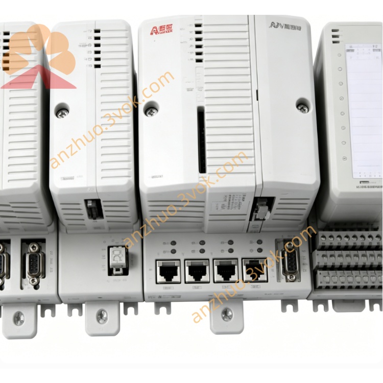
Rear golden finger backplane connector inserts into cabinet internal system bus to realize real-time data interaction and fault code transmission with auxiliary signal acquisition boards in rack. Front side terminal terminals directly connect field PT voltage transformer, CT current transformer, winding temperature measuring elements and thyristor trigger wiring terminals. Multiple onboard LED indicator lamps display power status, running mode, channel abnormal and system fault information for on-site inspection. Standard RS485 interface supports Modbus RTU protocol to upload operation data to upper SCADA monitoring system and complete remote parameter modification; reserved CAN communication interface can expand Profibus DP option to connect plant DCS and PLC system, local debug port supports handheld panel offline parameter setting and program downloading.
5.Core Functions
Collect multi-channel generator terminal voltage, stator current and rotor temperature analog signals from field instruments, filter and isolate input signals then transmit processed digital data to internal core control unit. Built-in optimized PID plus PSS power system stabilization algorithm calculates required excitation output value, outputs corresponding thyristor firing pulse to control rectifier module DC excitation current, stabilize generator terminal voltage and adjust unit reactive power output according to grid load variation. Equipped with comprehensive protection logic including overexcitation, underexcitation, loss of voltage, overcurrent and rotor overheating protection, automatically block trigger pulse and output interlock trip signal to cut excitation loop once fault happens. Run periodic automatic self-diagnosis for internal sampling circuit, power supply loop and communication channel, store fault codes locally for later maintenance inquiry, support generator grid paralleling auxiliary control and reactive power constant control mode switching.
6.Application Scenarios
Mainly installed in brushless excitation rectifier cabinet of medium and small synchronous generator sets for thermal power plants, hydropower stations, biomass power plants and distributed gas-fired power stations. Configured on excitation control cabinet of large synchronous drag motors used for mine main exhaust fan, cement rotary kiln main drive and petrochemical high-power compressor equipment to realize startup excitation control and steady-state voltage regulation of synchronous motor. Also widely applied for marine diesel generator set voltage stabilization and small wind power distributed generation unit excitation control system.
7.Operation and Maintenance Instructions
Cut off total cabinet AC input power before disassembly inspection or regular maintenance, wait more than 30 minutes for internal high-voltage capacitor full discharge to avoid electrostatic damage to onboard precision chips. Implement quarterly routine maintenance, use dry soft brush to clear accumulated dust on PCB surface and golden finger contact area, tighten all wiring terminals to eliminate poor contact caused by loose wiring. When excitation system occurs regulation deviation or protection trip fault, firstly check external PT/CT secondary circuit and peripheral wiring before replacing the whole module. Unauthorized disassembly of original onboard electronic components and arbitrary modification of internal core control parameters are strictly forbidden; replace complete new module when permanent internal hardware damage is verified after detection.
Get a Quote