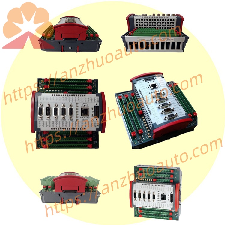
MOOG D137-002-001 RDIO16/16-0.5 Digital IO Expansion Module
Description
Model Explanation
D137: IO expansion module series for MSC system
002: Second-generation optimized hardware substrate, upgraded circuit anti-interference
001: 16 input 16 output standard digital IO configuration code, single channel 0.5A driving specification Technical Specifications
Electrical parameters
Power Supply: DC24V (18~36VDC), total machine power consumption ≤ 8W, working current 0.32A
Input Specifications: 16-channel NPN/PNP universal 24VDC digital input, optocoupler isolation
Output Specifications: 16-channel transistor digital output, single channel rated load 0.5A, maximum single-point peak 1A, cannot directly drive high-power solenoid valves
Response Speed: single-point signal acquisition response ≤ 0.5ms, bus refresh cycle 250μs
Dimensions: 122×167×84mm, IP20 protection, standard 35mm DIN rail installation
Environmental Conditions: operating temperature - 10℃~+60℃, storage and transportation - 35℃~+80℃, humidity 5%~95% RH without condensation, meets EN61000 industrial electromagnetic compatibility standards
Channel Resources
DI: 16 channels 24V isolated digital input
DO: 16 channels 24V isolated digital output
No analog input/outputs, no encoder interface (different from D137-001-010) Communication configuration
Internal bus: E-BUS dedicated high-speed bus, with a rate of 10 Mbps. Up to 8 modules of the same series D137 can be connected in series with the main controller.
Auxiliary interface: 1 RS232 debugging serial port. No onboard EtherCAT or Profibus external buses. Cannot independently form a networked upper-level PLC.
Interface and communication configuration
Double-layer green spring plug-and-unplug terminals on top and bottom, with digital input wiring on the top layer and digital output wiring on the bottom layer; side snap-type E-BUS bus port. Modules can be cascaded by connecting end to end without the need for external communication cables. Core function
Expand the main control switch quantity points, collect passive/active switch signals such as travel limit, pressure switch, equipment readiness, and fault alarm;
Output points drive intermediate relays, indicator lights, and small electromagnetic directional valves to achieve logic control for equipment start/stop and oil circuit connection/disconnection;
The full-channel photoelectric isolation of input and output ensures isolation from surge interference caused by on-site frequency converters and hydraulic solenoid valves;
The module has built-in channel fault self-check, and real-time upload of short-circuit and overcurrent points to D136 main control and record fault codes;
The MACS programming software uniformly configures addressing, and the points are seamlessly connected with the main control program for programming. Applicable scenarios
Expansion of EH speed control system switch points for turbine units, limit collection for fatigue testing machines for automotive components, logic control for aviation actuator test benches, interlock control for hydraulic press equipment, and expansion of switch quantities for small and medium-sized material testing equipment.
Instructions for Installation and Maintenance
Installed in the dry area of the control cabinet, away from locations with hydraulic oil mist and water vapor splashing;
When driving a large power load, an intermediate relay must be added; direct connection of the load exceeding 0.5A is prohibited;
Check and tighten the connection terminals every six months to check for oxidation and loosening hazards;
The E-BUS bus wiring should avoid large power power cables to reduce electromagnetic interference;
Annual inspection of the 24V power supply voltage, avoiding voltage fluctuations exceeding the rated ±10% range.
Get a Quote