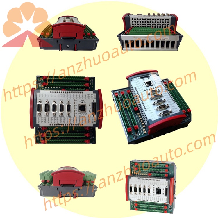
MOOG D137-001-010 MSCⅡ System IO Expansion Module
Description
Model Explanation
D137: Special IO Expansion Module Product Line for MSCⅡ System;
001: First-generation Hardware Substrate;
010: Standard IO Configuration Code, includes standard basic analog input/output + encoder interface, without additional external bus. Technical Specifications
Electrical parameters
Power Supply: DC24V (18~36VDC, ±10%), total machine power consumption ≤ 12W, working current 0.4A
AD/DA Accuracy: 16-bit analog-to-digital / digital-to-analog conversion, analog range ±10V, output drive 120mA, directly drives small power servo valve
Dimensions: 124mm×168mm×86mm, protection IP20, standard 35mm DIN rail snap-in installation
Operating Environment: working temperature - 20℃~+70℃, storage - 40℃~+85℃, humidity 5%~95% RH without condensation, complies with EN61000 EMC industrial immunity standard
Built-in IO Resources
Analog Input: 12 channels of 16-bit high-precision AI (±10V)
Analog Output: 6 channels of AO (±10V)
Digital Points: 24 channels of DI / 24 channels of DO
Feedback Interface: 2 channels of SSI / incremental encoder acquisition ports Communication configuration
Local bus: E-BUS (10 MHz high-speed internal bus, directly connected to D136 main controller, up to 8 D137 modules can be connected in series with a single main controller)
Auxiliary serial port: 1 RS232 debugging port, no onboard Profibus/EtherCAT external bus (distinguishing 011 model), unable to independently form a networked upper-level PLC
Interfaces and wiring
Separate upper and lower plug-and-unplug spring terminal blocks, upper end for digital signals, lower end for analog signals; side E-BUS connector terminal blocks enable module cascading, no additional wiring required. Core function
Expand multi-channel sensor acquisition, servo valve drive output, and encoder position feedback for the main control D136 series;
On-board signal filtering circuit to suppress electromagnetic interference caused by hydraulic system oil mist and frequency conversion equipment;
Self-check for faults, short circuit of channels and overvoltage are reported to the main control for alarm in real time;
MACS programming software for unified configuration, IO points can be directly addressed and called within the main control program. Applicable scenarios
Expansion of IO for the turbine electric-hydraulic speed regulation EH system, expansion of test points for the automotive component fatigue testing machine, multi-channel testing platform for material mechanics, and equipment for medium and small-sized hydraulic synchronous forming.
Installation and maintenance instructions
Install in the clean area of the control cabinet, away from the position where hydraulic oil splashes;
Tighten terminal connections every six months, check for oxidation and loosening;
Annual calibration of the zero points of the simulation channels to ensure the accuracy of force control / displacement acquisition;
Avoid laying E-BUS cascading cables parallel to power cables to reduce interference.
Get a Quote