MOOG D136-002-004 MSCⅡ Multi-Axis Servo Motion Controller
Description
Model Explanation
D136: MSCⅡ Controller Product Platform; 002: Second-generation Optimized Hardware Substrate; 004: Customized Configuration Code for Bus and IO, includes PROFIBUS-DP and extended analog/digital channels, distinct from the low-end bus versions of 002/003. Technical Specifications
Electrical parameters
Power supply: DC 24V (±10%, 18~36VDC), full load power consumption 45W, no-load operating current 0.3A, full load 0.8A
Main control chip: 32-bit floating-point RISC processor, 128MB running memory + 32MB flash memory, minimum servo operation cycle 250μs
Built-in I/O: 16 channels of 16-bit high-precision analog input, 8 channels of ±10V analog output (single channel maximum 120mA direct drive Moga servo valve); 32 digital inputs + 32 digital outputs; 4 channels of SSI / incremental encoder feedback interface
Dimensions: 124mm × 170mm × 85.5mm (width × depth × height), protection level IP20, standard 35mm DIN rail installation Communication configuration
Standard configuration: Dual CAN/CANopen, 2 RS232 interfaces, 100Mbps Ethernet, E-BUS internal expansion bus
Unique configuration: Built-in native PROFIBUS-DP slave interface (core feature of this model), RS port can be expanded with Modbus-RTU protocol
Environmental parameters
Operating temperature: -20℃ to +70℃; Storage temperature: -40℃ to +85℃; Environmental humidity: 5% to 95% RH, no condensation, meets national standards for industrial EMC anti-interference. Core function
Up to 8-axis synchronous three-loop PID closed-loop control, compatible with both hydraulic servo valves and servo motors as driving devices, precisely achieving the switching of force control, displacement control, and speed control;
Integrated embedded small PLC, without the need for an external PLC, can complete equipment interlock and sequential logic control;
E-BUS bus can be cascaded to expand IO modules, and the number of acquisition and drive points can be expanded as needed;
PROFIBUS bus directly connects to the upper PLC/DCS system to achieve networking and communication of the entire automation system;
Power-off parameters are long-term saved, and the data storage life can reach 10 years.
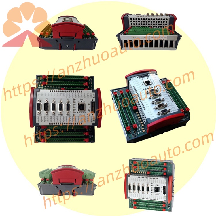
Interfaces and Wiring
Upper and lower layer plug-and-play red wiring terminals, the upper terminal is arranged with digital signal lines, and the lower terminal is arranged with analog signal lines; the cabinet is installed with side-by-side snap-fit guide rails, and the terminals come with short-circuit and overvoltage protection circuits. Applicable scenarios
Steam turbine electro-hydraulic speed regulation EH system, aviation actuator durability test bench, automotive component fatigue testing equipment, precision hydraulic forming press, multi-channel material mechanics comprehensive testing machine.
Operation and maintenance instructions
Install dust filters on the control cabinet to prevent hydraulic oil mist and dust from entering the components;
Conduct quarterly inspections of the 24V power supply voltage fluctuation range to prevent under-voltage and over-voltage operation;
Perform zero-point calibration of the analog channels in high-precision measurement and control scenarios every six months;
Keep away from corrosive gases and intense vibration working environments to avoid moisture and oxidation of the bus connectors.
Get a Quote