SGD7S-5R5A00A002
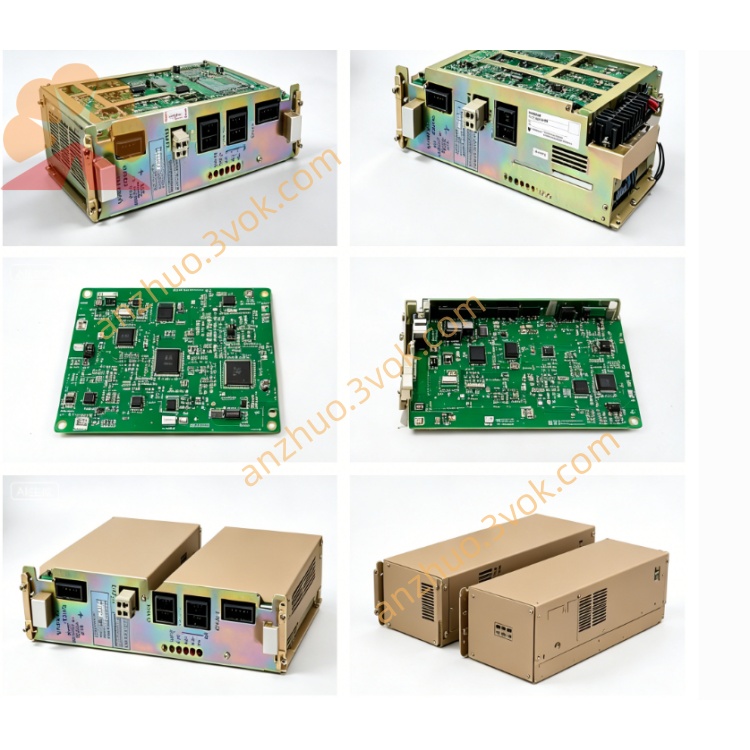
SGD7S-5R5A00A002 belongs to YASKAWA Sigma-7 high-performance single-axis AC servo amplifier, MECHATROLINK-III fieldbus command type servo driver designed to match SGM7J/SGM7A series 750W rated rotary AC servo motor, a mainstream high-response digital servo product upgraded from Sigma-V series by Yaskawa Electric. This model adopts full digital 32-bit floating-point control processor, reaching 3.1kHz speed loop response bandwidth for ultra-fast dynamic response and high-precision positioning control. The suffix 002 stands for standard STO safety terminal configuration and built-in dynamic brake circuit without external regenerative resistor by default; widely applied in precision automation equipment including CNC feeding mechanism, automatic dispensing equipment, PCB drilling machine, packaging positioning machinery and small robotic joint drive system. It supports full closed-loop feedback matching with 24-bit high-precision serial encoder equipped on matched servo motor to realize high-resolution positioning control.
Description
1. Product General Introduction
SGD7S-5R5A00A002 belongs to YASKAWA Sigma-7 high-performance single-axis AC servo amplifier, MECHATROLINK-III fieldbus command type servo driver designed to match SGM7J/SGM7A series 750W rated rotary AC servo motor, a mainstream high-response digital servo product upgraded from Sigma-V series by Yaskawa Electric. This model adopts full digital 32-bit floating-point control processor, reaching 3.1kHz speed loop response bandwidth for ultra-fast dynamic response and high-precision positioning control. The suffix 002 stands for standard STO safety terminal configuration and built-in dynamic brake circuit without external regenerative resistor by default; widely applied in precision automation equipment including CNC feeding mechanism, automatic dispensing equipment, PCB drilling machine, packaging positioning machinery and small robotic joint drive system. It supports full closed-loop feedback matching with 24-bit high-precision serial encoder equipped on matched servo motor to realize high-resolution positioning control.
2. Core Electrical Parameter Specifications
Rated input power supports single-phase or three-phase AC200V~240V power supply with allowable voltage fluctuation range -15%~+10%, rated frequency 50Hz/60Hz; main circuit rated continuous output current is 5.5Arms, instantaneous peak output current reaches 16.9Arms for short-time overload startup requirement. Rated applicable matched servo motor rated power is 0.75kW, control circuit power is independently powered by same AC200V level with rated input current 0.2Arms. Internal main circuit power loss is around 39W and control circuit power consumption is approximate 14W under normal working status. Standard communication interface is integrated MECHATROLINK-III high-speed industrial fieldbus which realizes multi-axis synchronous linkage, real-time parameter reading and program downloading with upper motion controller; reserved RS422 debugging port for SigmaWin+ upper computer software connection to complete parameter setting, waveform monitoring and fault diagnosis. Multi-layer built-in hardware protection includes overcurrent, overvoltage, overload, overheat, encoder disconnection, STO safety cutoff, regenerative overvoltage and external travel limit interlock protection to trigger shutdown and corresponding fault code output once abnormal working condition occurs automatically.
3. Environmental & Mechanical Specifications
Protection grade of the servo driver casing is IP20, only preventing large foreign solid particles invasion and forbidden to directly contact water splash or heavy oil mist environment. Allowable continuous operating ambient temperature range is from -5℃ to +55℃; spare storage temperature spans -20℃ to +65℃, applicable working environment relative humidity 10%~80%RH without internal condensation on circuit board and electronic components. The whole machine shell uses high-strength industrial plastic and aluminum alloy heat dissipation structure, natural air cooling design without built-in cooling fan for standard version; net weight of this driver is around 1.1kg, mounting mode is standard DIN guide rail or fixed hole wall-mounted installation on electrical cabinet inner board. The product conforms to CE, UL international electrical safety certification, STO safety function reaches SIL3 and PL-e CAT3 safety standard meeting international machinery safety specification requirement.
4. Complete Core Functional Description
4.1 Control Mode
Main command receiving mode relies on MECHATROLINK-III bus digital position instruction; via parameter modification users can switch temporarily to analog speed control or analog torque control mode for special debugging application, electronic gear function is built-in with adjustable ratio in wide range to flexibly coordinate mechanical reduction ratio without mechanical part modification. Full closed-loop control function is optional by connecting external linear scale feedback signal to realize ultra-precise full closed positioning eliminating mechanical backlash error.
4.2 Intelligent Tuning & Suppression Functions
Multiple auto-tuning modes include no-load static auto-tuning, on-load dynamic auto-tuning and inertia identification auto-tuning; the driver automatically identifies motor rotor inertia and optimizes position loop, speed loop gain to shorten field debugging cycle greatly. Built-in multi-stage mechanical vibration suppression algorithm, low-frequency resonance suppression and ripple torque compensation function effectively eliminate equipment low-speed jitter and high-frequency resonance problem to improve operating smoothness and positioning precision. Standard JOG inching operation function supports manual motor forward/reverse jog without upper controller connection for mechanical stroke test before automatic operation.
4.3 Safety & Auxiliary Functions
STO safe torque off function is pre-installed as standard configuration; when external safety contact signal cuts off STO terminal input, servo torque output is shut down immediately conforming to machine safety design requirement. Complete fault history storage function records up to recent dozens of abnormal alarm codes with corresponding occurrence runtime for maintenance troubleshooting; real-time monitoring items include actual motor rotating speed, output torque ratio, position deviation, bus voltage and internal operating temperature, all data can be checked via upper computer software or optional digital operation panel. Dynamic brake circuit is built inside driver to realize rapid motor stopping during power failure or emergency stop triggering to avoid mechanical inertial sliding.
5. Wiring, Operation & Daily Maintenance Guidance
Before power-on wiring, strictly distinguish main circuit power terminal, motor winding output terminal, encoder feedback socket, CN1 safety I/O terminal and MECHATROLINK bus terminal to prevent wrong wiring burnout; reliable grounding of driver protective earth terminal is mandatory for anti-interference and electrical safety protection. Complete motor parameter auto-tuning after initial wiring and power-on before formal automatic running; set proper torque limit and speed limit parameter during JOG test to avoid mechanical collision caused by misoperation high-speed movement. For regular maintenance work, periodically clean dust accumulated on driver surface heat dissipation gap, tighten loose terminal screws and inspect cable outer insulation ageing condition; cut off main power supply and wait at least 15 minutes for internal large-capacity capacitor full discharge before opening driver casing for internal component maintenance to prevent electric shock hazard. When storing spare driver for long term, place it in dry constant-temperature warehouse away from corrosive gas, dust and direct sunlight.
Get a Quote