SGDA-01AP
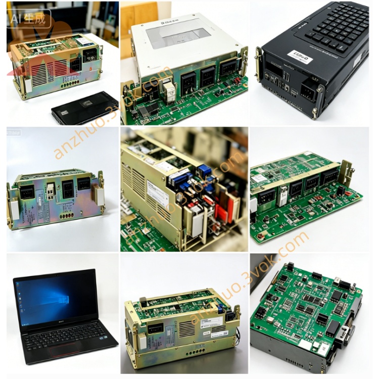
SGDA-01AP is Yaskawa Sigma series compact AC servo driver with 100W rated capacity, designed for driving matching SGM series 100W AC servo motors. This is a classic discontinued digital position-control servo amplifier widely adopted in small precision automation equipment including precision feeders, small dispensing machines, PCB micro-processing devices and light-load positioning transmission mechanisms. It receives position command via pulse signal from external PLC or motion controller and performs closed-loop servo control for speed and position. The internal control circuit is coated with protective insulating paint to enhance resistance against dust and slight moisture under regular workshop operating conditions. Surplus available products on market are factory refurbished and pre-tested spare units for equipment maintenance replacement.
Description
1. Product Overview
SGDA-01AP is Yaskawa Sigma series compact AC servo driver with 100W rated capacity, designed for driving matching SGM series 100W AC servo motors. This is a classic discontinued digital position-control servo amplifier widely adopted in small precision automation equipment including precision feeders, small dispensing machines, PCB micro-processing devices and light-load positioning transmission mechanisms. It receives position command via pulse signal from external PLC or motion controller and performs closed-loop servo control for speed and position. The internal control circuit is coated with protective insulating paint to enhance resistance against dust and slight moisture under regular workshop operating conditions. Surplus available products on market are factory refurbished and pre-tested spare units for equipment maintenance replacement.
2. Electrical Specifications
The driver accepts single-phase AC 200V to 230V input power at 50/60Hz frequency, with rated input current of 2.5A and rated output power of 100W. It outputs adjustable three-phase AC voltage to drive matched servo motor with rated output current of 0.87A, supporting maximum output frequency up to 300Hz to satisfy high-speed rotation demand of paired motors. The control terminal accepts two mainstream pulse input types: open collector and line driver pulse signals for position instruction input. Multiple built-in protection functions cover overcurrent, overvoltage, overload, overheat, encoder disconnection and regenerative surge voltage protection; the driver automatically cuts off power output and triggers corresponding fault alarm once abnormal operating parameters are detected. Control power is derived from the same input AC power source without separate external power supply requirement.
3. Environmental and Mechanical Requirements
The servo unit features IP20 enclosure protection, which only prevents intrusion of large solid particles and must be installed inside sealed control cabinet to avoid direct water splash, heavy oil mist and dense conductive dust. Continuous working ambient temperature ranges from 0℃ to +55℃, while long-term storage temperature falls between -20℃ and +60℃. Allowed relative working humidity is from 10% to 80 percent with no condensation allowed on internal circuit boards. The driver is designed for DIN rail or screw fixed installation inside electrical cabinet, with compact overall structure and natural air cooling mode. The product complies with CE and UL international electrical safety standards for industrial application.
4. Main Functions
This driver uses position control as default working mode; users can switch to speed or torque control mode via parameter setting for temporary equipment debugging needs. It is equipped with electronic gear function featuring wide adjustable gear ratio, helping match mechanical transmission ratio without modifying physical mechanical parts. Built-in automatic gain tuning identifies motor parameters automatically after initial power-on to optimize servo loop gain and shorten field debugging period. Independent JOG jogging function allows manual forward and reverse motor operation without connecting external motion controller for mechanical stroke inspection. Real-time operational data such as actual rotating speed, output current and position deviation can be checked via front panel digital display, and recent fault codes are stored inside memory for convenient maintenance troubleshooting. Separate terminal blocks are arranged for main power input, motor power output, encoder connection and control signal wiring respectively for clear wiring layout.
5. Installation and Maintenance Instructions
Confirm input voltage strictly matches rated AC 200V~230V before power connection to avoid component damage from wrong voltage access, and reliably connect protective grounding terminal for safety and anti-interference purpose. Complete auto-tuning procedure after first wiring and power-on before formal automatic operation; set reasonable speed limit during jog test to prevent unexpected mechanical collision. For periodic maintenance, regularly clean dust blocking heat dissipation vents and check tightness of wiring terminals as well as ageing status of connecting cables. Cut off main power supply and wait no less than ten minutes for internal capacitor residual voltage full discharge before opening driver housing for internal repair work to prevent electric shock accidents. Store spare drivers in dry and ventilated warehouse away from corrosive gas and direct sunlight for long-term preservation.
Get a Quote