SGDA-01BP
SGDA-01BP is a classic discontinued Sigma Series 100W AC servo amplifier from Yaskawa, designed to match SGM-01A series 100V-rated servo motors. Compared with SGDA-01AP which uses AC200V input, SGDA-01BP is specified for single-phase AC100~115V power supply. It is a pulse command type position-control driver widely used for small precision automation equipment such as dispensing machines, miniature positioning feeders, laboratory instrument drives and compact automated assembly modules. The internal PCB is coated with protective insulating varnish to improve resistance against dust and mild moisture inside control cabinets. Most available products on the market are pre-tested refurbished spare units for equipment maintenance replacement.
Description
1. Product Overview
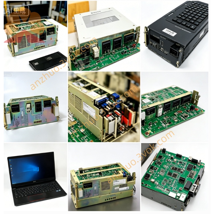
SGDA-01BP is a classic discontinued Sigma Series 100W AC servo amplifier from Yaskawa, designed to match SGM-01A series 100V-rated servo motors. Compared with SGDA-01AP which uses AC200V input, SGDA-01BP is specified for single-phase AC100~115V power supply. It is a pulse command type position-control driver widely used for small precision automation equipment such as dispensing machines, miniature positioning feeders, laboratory instrument drives and compact automated assembly modules. The internal PCB is coated with protective insulating varnish to improve resistance against dust and mild moisture inside control cabinets. Most available products on the market are pre-tested refurbished spare units for equipment maintenance replacement.
2. Electrical Specifications
The driver takes single-phase AC100V~115V, 50/60Hz main power input with rated input current of 4.5A. Its rated continuous output current is 2.2Arms and peak overload current reaches 7.1Arms for short-time startup load; maximum output three-phase voltage is AC115V. The control circuit shares the same input power source without independent auxiliary power supply.
For command interface, the CN1 control connector supports two standard pulse input formats including line driver 5V differential signal and open-collector 24V signal, accepting either CW/CCW dual-pulse or pulse-plus-direction instruction modes for position control. Extra digital I/O terminals are arranged for servo enable, external limit input, fault signal output, JOG control and fault reset functions. A built-in RS232 port enables parameter setup and status monitoring via Yaskawa SigmaWin PC debugging software, while no fieldbus communication is equipped on this standard model.
Multiple hardware protection functions are fully integrated inside the driver, covering overvoltage, overcurrent, overload, overheat, encoder disconnection and regenerative surge protection. The unit automatically cuts off motor output and displays corresponding fault codes on front digital indicator once abnormal conditions are detected.
3. Environmental and Mechanical Specifications
The enclosure protection rating is IP20, which only blocks large solid particles; installation inside closed electrical cabinet is mandatory to avoid direct water splash, heavy oil mist and conductive floating dust. Continuous working ambient temperature ranges from 0℃ to +55℃, and long-term storage temperature is between -20℃ and +85℃. Allowed working relative humidity falls within 10% to 90%RH with no condensation permitted on internal components.
The driver adopts natural air cooling without built-in cooling fan, and supports standard DIN rail mounting or direct screw fixing inside cabinet. Its approximate net weight is 0.9kg and the product has obtained CE and UL industrial safety certifications.
4. Main Functional Features
Default operation mode is digital pulse position control; users may switch to speed control or torque control mode by modifying internal parameters for equipment commissioning. The auto-tuning function automatically identifies motor inertia and optimizes speed-loop and position-loop gain to shorten on-site debugging time. Built-in electronic gear function provides wide adjustable ratio range to match mechanical transmission setup without changing physical mechanical parts.
Independent JOG inching function allows manual forward and reverse motor operation directly from front panel without connecting external motion controller for mechanical stroke inspection. Historical fault codes are stored in onboard memory to facilitate maintenance troubleshooting. An integrated dynamic brake circuit realizes fast motor stopping during emergency stop or sudden power loss to prevent mechanical sliding caused by inertia.
5. Installation and Maintenance Guidelines
Verify input power voltage is strictly within AC100~115V before wiring to avoid burnout from incorrect high voltage access, and connect the protective grounding terminal reliably for safety and anti-interference performance. Complete motor auto-tuning after initial wiring and power-on before formal automatic operation, and set proper speed limit value during JOG test to prevent unexpected mechanical collision.
During regular maintenance, regularly clean dust accumulated around cooling vents and check tightness of terminal screws as well as insulation condition of connecting cables. Cut off main power supply and wait no less than 10 minutes for full discharge of internal capacitor residual voltage before opening the driver casing for internal repair to prevent electric shock risk. Keep unused spare drivers stored in dry and ventilated warehouse away from corrosive gas and direct sunlight.
Get a Quote