JANCD-MB21-BOARD-DF8101521-CO-REV-C
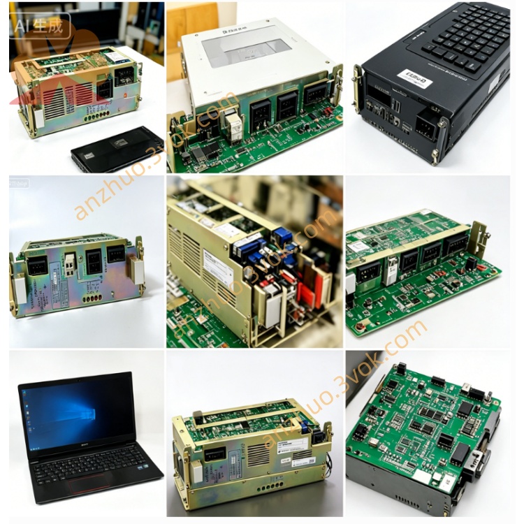
JANCD-MB21 with part code DF8101521-C0 REV.C is the original YASKAWA YASNAC CNC main control motherboard developed and produced in Japan, serving as the core CPU master board for classic YASNAC CNC control system and matching Mori Seiki, Hitachi Seiki and other series of lathes, vertical machining centers, including previously mentioned TSV-C37 machine tool equipment. This mainboard works cooperatively with UGRMEM series storage boards, SZRCR-NTU02 power modules and various axis control daughter boards inside the control cabinet, undertaking core tasks of CNC operation logic calculation, servo motion instruction transmission, system parameter storage and whole machine I/O signal scheduling. It adopts standard cabinet slot plug-in installation structure, directly inserted into the system backplane card slot for mechanical fixation and bus connection. Original formal production of this revision REV.C has been discontinued by Yaskawa; current market supply mainly consists of tested second-hand disassembled parts and professionally refurbished spare boards for equipment maintenance replacement of old-model CNC machining equipment.
Description
1. Product Introduction
JANCD-MB21 with part code DF8101521-C0 REV.C is the original YASKAWA YASNAC CNC main control motherboard developed and produced in Japan, serving as the core CPU master board for classic YASNAC CNC control system and matching Mori Seiki, Hitachi Seiki and other series of lathes, vertical machining centers, including previously mentioned TSV-C37 machine tool equipment. This mainboard works cooperatively with UGRMEM series storage boards, SZRCR-NTU02 power modules and various axis control daughter boards inside the control cabinet, undertaking core tasks of CNC operation logic calculation, servo motion instruction transmission, system parameter storage and whole machine I/O signal scheduling. It adopts standard cabinet slot plug-in installation structure, directly inserted into the system backplane card slot for mechanical fixation and bus connection. Original formal production of this revision REV.C has been discontinued by Yaskawa; current market supply mainly consists of tested second-hand disassembled parts and professionally refurbished spare boards for equipment maintenance replacement of old-model CNC machining equipment.
2. Detailed Technical Content & Specifications
This main control board is powered by DC5V system bus supplied from cabinet internal switching power supply without independent external power access, with rated overall working current controlled below 1.2A and shared grounding design together with cabinet power distribution system to suppress power supply interference during equipment startup and shutdown. The board integrates built-in core arithmetic processor, onboard nonvolatile storage circuit matched with external UGRMEM series memory card to store user machining programs, coordinate origin data, servo gain parameters, fault record information and system configuration data; backup battery circuit is reserved on PCB for short-term power-off data protection of core parameters when cabinet main power is cut off.
Multiple dedicated gold finger expansion slots are reserved on board edge for docking axis control boards, digital input/output expansion boards and communication adapter boards, realizing flexible system function expansion according to different machine tool configuration requirements. Complete hardware self-test circuit is embedded inside the circuit; automatic power-on diagnosis will be executed every time the equipment is powered up, and corresponding fault alarm codes will be fed back on the CNC operation panel once bus communication failure, storage abnormality or peripheral card docking error is detected.
For environmental working conditions, its allowable continuous operating ambient temperature ranges from 0℃ to 40℃, and long-term storage temperature is between -20℃ and +55℃; applicable working relative humidity is 10%~80% without surface condensation on PCB components. The installation environment needs to stay away from conductive metal dust, corrosive cutting fluid volatile vapor and oil mist to avoid circuit short circuit or component corrosion damage. Multiple levels of protection circuits including overvoltage, overcurrent and surge suppression are integrated on PCB, effectively resisting instantaneous voltage fluctuation from cabinet power grid and abnormal load feedback from servo driver to prevent mainboard core chip breakdown.
3. Installation & Operation Precautions
Anti-static protection operation must be implemented during disassembly and replacement, wearing standard anti-static wristband to avoid static electricity damaging onboard integrated chips; all stored machine tool parameters should be fully backed up to external storage medium before removing the mainboard to prevent data loss caused by parameter clearing after board replacement. Confirm correct slot direction before plugging into cabinet backplane, prohibit forced reverse insertion which may damage gold finger contacts and onboard peripheral circuits. After installation completion, conduct no-load power-on debugging first to finish system self-check and parameter recovery, then carry out trial running of each machine tool axis to verify stable communication between mainboard and servo control units. Regular maintenance requires periodic cleaning of accumulated dust on PCB surface and slot connectors to guarantee long-term stable contact performance of bus connection.
Get a Quote