JANCD-YSF24
JANCD-YSF24-E is Yaskawa original functional safety expansion I/O logic board exclusively configured for DX200 robot controller system, categorized into YSF series safety PCB and used as auxiliary safety expansion module matching standard safety mainboard JANCD-YSF22-E/YSF22B-E inside DX200 control cabinet. This board complies with IEC61508 SIL3 functional safety standard and Category3 safety specification, specially designed to expand extended functional safety input and output signals that cannot be processed by basic YSF22 safety board, widely used for collaborative robot, safety area monitoring, axis travel limit and speed restriction application scenarios on DX200 robot system. It is mounted on dedicated vacant slot of YBB21 backplane together with YCP21 main CPU board, YIF01 servo interface board and YSF22 basic safety board to form complete full safety control architecture of DX200 cabinet.
Description
1. Product Brief Introduction
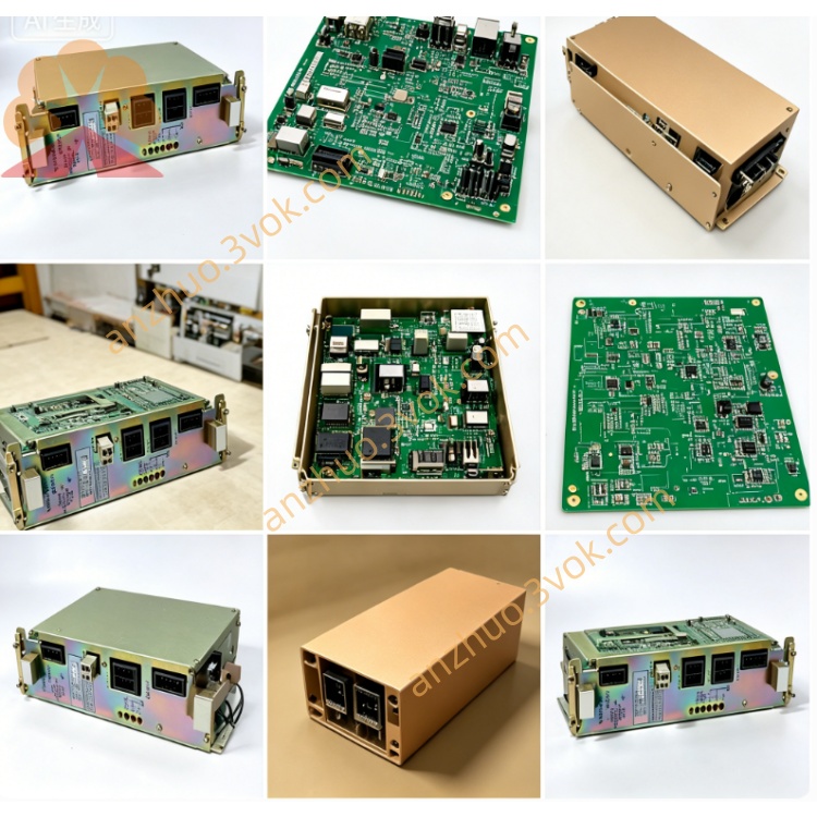
JANCD-YSF24-E is Yaskawa original functional safety expansion I/O logic board exclusively configured for DX200 robot controller system, categorized into YSF series safety PCB and used as auxiliary safety expansion module matching standard safety mainboard JANCD-YSF22-E/YSF22B-E inside DX200 control cabinet. This board complies with IEC61508 SIL3 functional safety standard and Category3 safety specification, specially designed to expand extended functional safety input and output signals that cannot be processed by basic YSF22 safety board, widely used for collaborative robot, safety area monitoring, axis travel limit and speed restriction application scenarios on DX200 robot system. It is mounted on dedicated vacant slot of YBB21 backplane together with YCP21 main CPU board, YIF01 servo interface board and YSF22 basic safety board to form complete full safety control architecture of DX200 cabinet.
2. Detailed Product Content
2.1 Core Working Functions
This board focuses on collecting and transmitting extended user-defined functional safety I/O signals, realizing independent safety logic judgment separated from basic emergency-stop safety circuit of YSF22 main safety board. It receives external safety input signals including safety zone proximity switch, robot overtravel dual-channel limit sensor, speed monitoring trigger signal and peripheral fixture safety interlock switch, then conducts redundant dual-circuit safety logic verification internally. After signal processing, it exchanges all safety data with main CPU via backplane bus, feeds abnormal safety status to controller system and outputs corresponding safety cutoff command to YIF01 servo board when preset safety threshold is triggered, to restrict robot operating speed or cut off servo power supply partially or fully. Besides, it outputs safety status feedback signal to external peripheral equipment to realize interlock linkage with surrounding automation production line. All signal circuits adopt dual redundant wiring design to avoid safety failure caused by single line open or short circuit fault.
2.2 Electrical Parameter Details
The board gets DC24V ±10% operating power supply directly from YBB21 cabinet backplane slot, maximum rated power consumption is about 11W, built-in 1A slow-blow protective fuse on PCB for onboard circuit overcurrent protection. All functional safety digital input ports support universal sink/source DC24V signal access, each input point rated working current ranges from 3mA to 5mA, input valid state is DC24V powered on and invalid for open circuit. Safety output terminals adopt optocoupler isolated circuit design, each output load is limited within DC24V 0.45A for safety interlock driving use.
2.3 Ambient Working Condition
Standard operating ambient temperature scope is -10 degree Celsius to +55 degree Celsius, storage temperature ranges from -25 degree Celsius to +70 degree Celsius; applicable relative humidity is 30% to 80%RH under non-condensing environment, forbidden to install in space with corrosive gas, welding spatter, conductive dust and strong high-frequency electromagnetic interference from inverter or welding machine. The board adopts passive natural air cooling mode without built-in cooling fan, relying on cabinet internal natural convection for heat dissipation.
2.4 Onboard Connector Definition
CN200 is gold finger backplane bus connector plugged into YBB21 backplane, responsible for bidirectional data communication between YSF24 expansion safety board and YCP21 main CPU, no extra external wiring needed. CN220 is exclusive external functional safety I/O connector matched with corresponding safety terminal sub-board, used for field wiring connection of all expanded safety input and output signals including safety area switch, limit signal and linkage output signal. Another reserved auxiliary connector is for factory debugging and future customized safety function expansion, normally left vacant during regular on-site use.
2.5 Onboard LED Indicator Explanation
Green PWR indicator stands for power supply status, steady lighting means DC24V input is normal, extinguished status indicates onboard fuse blow or backplane slot power abnormal. Green RUN lamp represents bus communication condition, slow continuous flicker shows normal data exchange with main CPU and YSF22 main safety board, permanent off means backplane contact failure or communication bus breakdown. Orange SAFE lamp reflects overall extended safety loop status, steady on represents all expanded safety input loops closed and safety function standby ready, off state means any expanded safety switch triggered and safety interlock activated. Red ERR fault lamp keeps steady lighting when dual-channel input signal inconsistency, wiring short or internal logic fault occurs on expanded safety circuit, intermittent flicker stands for temporary signal interference or DIP switch setting error.
2.6 DIP Switch Setting Instruction
S1 DIP coding switch is set on PCB surface and all adjustment operations must finish under full cabinet power-off status. BIT1 to BIT2 are used for board station address definition, factory default fixed address matching DX200 system and random modification is prohibited; BIT3 sets input signal logic of safety limit switch, ON position corresponds to high level trigger with DC24V effective, OFF position matches normally closed contact open trigger mode; BIT4 to BIT6 are factory reserved setting pins and need to remain OFF position permanently without arbitrary adjustment.
2.7 Standard Installation and System Configuration Steps
Before board installation, completely disconnect cabinet main AC power supply and wait more than 15 minutes for internal high voltage capacitor full discharge to prevent residual voltage damage to electronic components. Adjust DIP switch parameters according to on-site external safety switch wiring specification firstly, then align PCB gold finger with specified empty slot on YBB21 backplane and insert board firmly until fixed buckle locks tightly. Complete external safety equipment wiring via CN220 matched terminal block and do single-point grounding for all shielding wire layers on cabinet earth bar. After finishing wiring, restore cabinet power supply, DX200 controller automatically identifies YSF24 expansion safety board during startup without manual hardware option setup via teach pendant. When replacing brand new YSF24 board, just reboot controller to complete automatic parameter matching; users can modify expanded safety signal allocation path via teach pendant menu of system safety setting page after system startup.
2.8 Common Troubleshooting Guidance
If PWR indicator always off, first check onboard 1A fuse burnout condition and replace with same specification fuse, then re-plug YSF24 board and test DC24V output voltage of corresponding backplane slot. When SAFE lamp permanently off and robot cannot execute preset safety area speed limit function, check all external expanded safety switch wiring circuit for open or short fault and recover temporarily with jumper wire for segmented troubleshooting. Red ERR lamp steady lighting mainly caused by unmatched DIP setting and inconsistent dual-channel redundant wiring, recheck switch setting and field wiring order respectively. RUN lamp off with normal power supply is mostly due to poor gold finger contact between board and backplane, clean gold finger with anhydrous alcohol and reinstall the board again.
2.9 Daily Maintenance Notes
All disassembly, wiring and maintenance operations must be carried out under full power-off state of robot control cabinet. Conduct regular maintenance every six months, clean accumulated dust on PCB surface with dry lint-free cloth and inspect connector terminals looseness and cable insulation aging condition. Once the board is confirmed damaged, overall replacement is recommended and unauthorized disassembly of onboard discrete electronic components is forbidden to avoid secondary damage to circuit structure. Keep PCB away from welding arc splash, moisture and strong electromagnetic radiation environment during long-term equipment operation.
Get a Quote