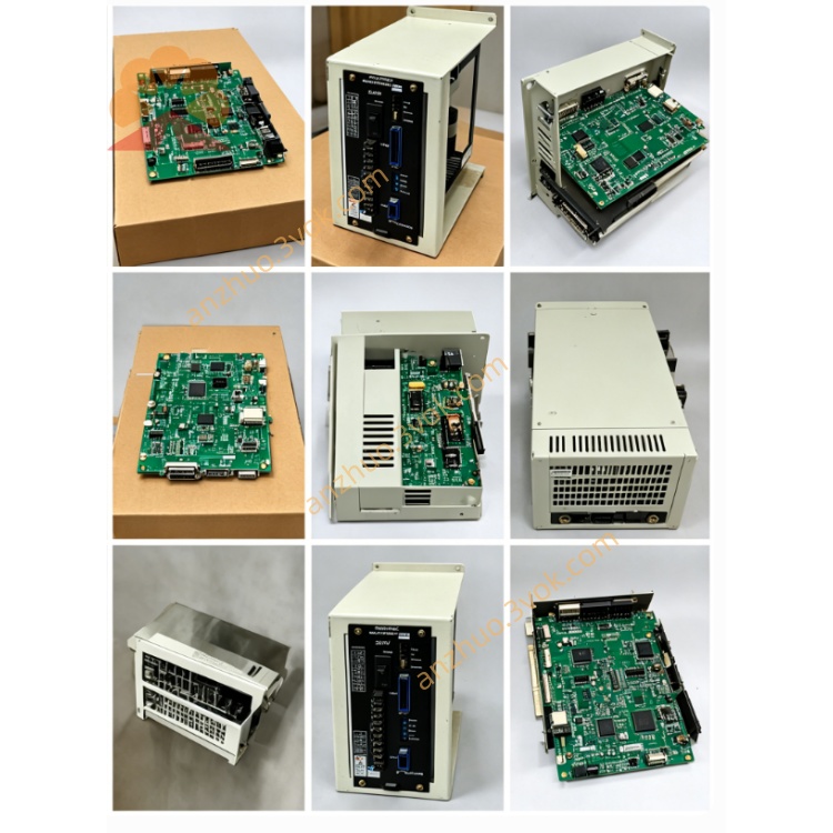
JANCD‑YCP02‑E DX200 Conveyor Sync / ComArc Welding Tracking Board
Description
1. General Information
Model: JANCD‑YCP02‑E (YCP02‑E)
Manufacturer: Yaskawa Electric Corporation
Applicable Controller: Motoman DX200 Robot Controller (not for DX100)
Function: Conveyor synchronization & ComArc seam tracking option board
Role: Handles up to 3 conveyor encoders for dynamic robot synchronization; supports ComArc welding seam tracking and external sensor interfacing
Type: Option board (not a CPU board) – DX200 main CPU is JANCD‑YCP21‑E
2. Specifications
Processor: High‑performance MCU
Encoder Inputs: 3 channels (incremental, differential/collector‑open compatible)
Communication Interfaces:
Ethernet 10/100 Mbps
RS‑485
Dedicated sensor/welding I/F
Memory: 16 MB RAM, 8 MB Flash ROM
Power Supply: DC 24 V ±10% (from backplane)
Power Consumption: Max 15 W
Operating Temperature: ‑10 °C to +55 °C
Storage Temperature: ‑20 °C to +70 °C
Humidity: 30%–85% RH (non‑condensing)
Dimensions (W×H×D): Approx. 100 × 60 × 35 mm
Weight: Approx. 0.3 kg
3. On‑Board Connectors & LEDs
Connectors
CN121: Encoder input (3‑channel combined port)
CNxxx: Ethernet
CNxxx: RS‑485
CNxxx: System bus (to YBB21 backplane)
LED Indicators
PWR: DC24V power good
RUN: Board active (flashing = normal)
ERR: Fault (hardware/config/comm)
COM: Communication activity
4. Required Boards & Compatibility
Required (DX200 System)
JANCD‑YCP21‑E: Main CPU board
JANCD‑YIF01‑2E: Robot I/F board
JANCD‑YSF21‑E: Safety CPU board
YBB21: Backplane (DX200)
Compatibility
✅ DX200 + YBB21 + YCP21‑E
❌ DX100 (uses YCP01 series; no YCP02 slot)
5. Installation Procedure
Power OFF: Turn off main power; wait 15 minutes for capacitor discharge.
Access Cabinet: Open front door; locate dedicated option slot on YBB21 backplane.
Insert Board: Align with guides; push firmly until fully seated (latch clicks).
Connect Cables:
CN121 → Conveyor encoder(s)
Ethernet/RS‑485 → Peripherals (if used)
Close Cabinet: Secure door; restore main power.
Verify: Check PWR ON + RUN flashing; confirm encoder/sensor communication.
6. Encoder Connection (CN121)
Signal: Incremental (PA, /PA, PB, /PB, +5V, 0V, Shield)
Max Count Frequency: 1 MHz
Cable: Twisted pair, shielded; max length 50 m
7. Troubleshooting
PWR LED OFF
Check DC24V supply to option slot
Verify YBB21 backplane power
Inspect system bus connector
RUN OFF / ERR ON
Re‑seat board; check for bent pins
Verify YCP21‑E CPU and YIF01‑2E I/F board
Check encoder wiring and power
Encoder Sync Failure
Verify encoder type (incremental) and wiring
Check CN121 pinout and shield grounding
Test with known‑good encoder
Communication Fail (Ethernet/RS‑485)
Check cable/connector integrity
Verify IP/serial parameters
Monitor COM LED for activity
8. Maintenance
6‑Month Inspection: Connector tightness, dust removal, LED status check
Cleaning: Use dry, lint‑free cloth; avoid touching gold contacts
Service Life: 5–8 years; replace if burned, corroded, or unstable
9. Key Differences (YCP01 / YCP21 / YCP02)
YCP01‑E: DX100 main CPU
YCP21‑E: DX200 main CPU
YCP02‑E: DX200 option board (conveyor sync / ComArc tracking)
Get a Quote