MRY01B-1
Description
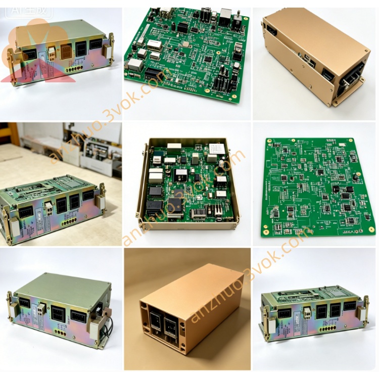
1. Product Overview
2. Core Functions
Digital signal input & relay output management for robot peripheral auxiliary equipment: safety door interlock, air pressure detection, hydraulic/clamping signal, external solenoid valve & auxiliary motor on-off control.
Communicate with main CPU via cabinet backplane bus, execute robot system ladder program to realize peripheral auxiliary logic control triggered by robot program instructions.
Built-in optocoupler isolation circuit and multiple onboard relays to separate DC24V field circuit and internal logic circuit for surge & interference prevention.
3. Electrical & Environmental Parameter
Rated power supply: DC24V input, total max allowable output current: 2A
Operating ambient: 0℃~40℃, relative humidity 10%~80% non-condensing, max applicable altitude ≤1000m above sea level
Net weight: approx 390g, industrial standard PCB material
4. Common Fault Performance
Robot peripheral components malfunction: safety door alarm, external valve cannot switch on/off, air pressure abnormal warning, caused by aging onboard relays or oxidized terminal pins.
System pop-up peripheral I/O fault alarm after power-on, partial auxiliary instruction invalid, usually from blown onboard fuse or damaged control IC chip.
Single channel no input detection signal or no relay output, resulting from damaged corresponding optocoupler or relay component.
5. Replacement & Safety Operation
Cut off robot main AC power completely, wait over 15 minutes for cabinet residual voltage discharge before disassembly; hot plugging is strictly forbidden to avoid burnout of backplane and main control board.
Mark all external terminal wiring order before unplugging cables, pull out faulty board and install replacement board into original slot position.
Restore all wiring per original marks, power on robot and conduct full test on safety interlock, peripheral pneumatic/hydraulic auxiliary actions to confirm all I/O functions normal without error code.
Get a Quote