mycEntEr-0
Description
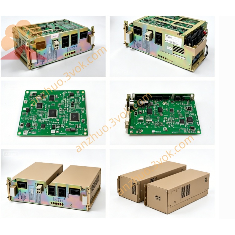
1. Product Overview
2. Core Functions
Serve as central data bridge between main CPU backplane and peripheral relay I/O boards (MRY01B series), realize high-speed bus data exchange of robot internal ladder logic signals.
Process external host communication signal, support peripheral equipment linkage including fixture, conveyor and auxiliary hydraulic/pneumatic station.
Complete system power logic distribution for cabinet slot boards, monitor operating status of onboard I/O modules and feed fault code back to robot teach pendant in real time.
3. Electrical & Environmental Specification
Power supply: +5V logic power from cabinet backplane, auxiliary DC24V for signal circuit
Operating temperature: 0℃ ~ +40℃; storage temperature: -20℃ ~ +70℃
Ambient humidity: 10%~80% RH non-condensing; max applicable altitude ≤1000m
Approx net weight: 420g, standard industrial anti-interference PCB layout
4. Typical Fault Symptoms
Robot random I/O alarm, abnormal safety door interlock, partial solenoid valve no output, caused by aging bus interface chip or poor gold finger contact.
Power-on system startup stuck with communication error code, unable to enter robot main program, due to blown onboard small fuse or damaged communication IC.
Partial M-code auxiliary instructions invalid, tool/clamp action out of control from local circuit component breakdown.
5. Replacement Operation & Safety Rules
Cut off total robot AC main power, wait over 15 minutes for residual electricity discharge inside control cabinet; hot swapping is strictly forbidden.
Mark all plug-in cable positions before removing wiring, extract faulty MYCENTER-0 board and install replacement board into original backplane slot.
Recover all connected wires following original marks, power on equipment, run full test of safety interlock, peripheral pneumatic and clamping auxiliary functions to confirm no error alarm.
Get a Quote