MRY01-3
Description
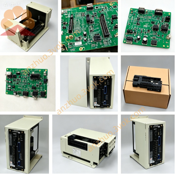
1. Product Overview
2. Main Functions
Collects all machine peripheral digital input signals and drives output loads including coolant pump, lubrication system, ATC tool changer, workpiece clamping cylinder, axis limit switches and safety door interlock signals.
Exchanges data with main CPU via backplane bus and executes PMC ladder program to realize auxiliary functions triggered by M codes such as coolant on/off and tool swap.
Adopts onboard optocoupler isolation and relay circuits to separate field DC24V circuit from internal CNC logic circuit for anti-interference protection.
3. Electrical and Installation Details
Power input: +5V logic power from cabinet backplane, external DC24V for field I/O circuit
Operating environment: 0℃~+50℃; storage temperature: -20℃~+70℃, relative humidity 10%~85% non-condensation
Mounting: Plug-in slot installation on cabinet main backplane beside memory boards
4. Common Faults
Abnormal tool change, unavailable coolant control or random limit alarm, usually caused by aged onboard relays, oxidized PCB traces or poor terminal contact.
System displays I/O error after power-on and partial M-code invalidation resulting from blown internal fuses or damaged control chips.
No input signal or no output drive on single channel due to breakdown of corresponding optocoupler or relay.
5. Replacement Procedures
Cut off the 3-phase main AC power of machine and wait over 15 minutes for residual electric charge discharge inside cabinet.
Mark all external connecting wires before disconnection, remove the faulty board and install replacement unit into original slot.
Reconnect all cables according to original marks, switch on power and test all auxiliary actions such as tool change and coolant operation.
Get a Quote