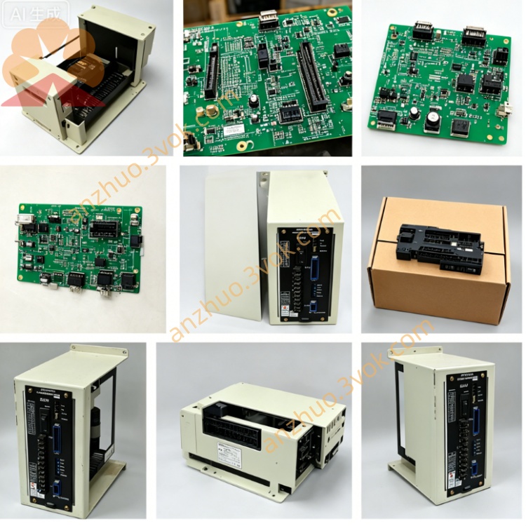
JANCD-YCP01-E (DX100 CPU Board)
Description
1. General Information
2. Specifications
Processor: 32-bit RISC, 120 MHz
Memory:
Flash: 1 MB (system firmware/programs)
RAM: 64 KB (execution memory)
Power Supply: DC 24 V ±10% (internal cabinet supply)
Power Consumption: Max 15 W
Operating Temperature: 0 °C to +55 °C
Storage Temperature: -20 °C to +70 °C
Humidity: 30%–85% RH (non-condensing)
Dimensions (W×H×D): Approx. 84 × 95 × 60 mm
Weight: Approx. 0.40 kg
Mounting: Dedicated CPU slot on JANCD-YBB01 backplane
3. On-Board Connectors & Layout
CN101: Teach Pendant – connects to DX100 teach pendant
CN102: Ethernet – 10/100 Mbps (program upload/download, remote access)
CN103: RS-232 – serial communication (legacy peripherals)
CN104: RS-485 – serial communication (I/O modules, vision)
CN105: System Bus – to YBB01 backplane (power + data)
CN106: CF Card Slot – for program/data backup/restore
CPU: Main processor (shielded)
Flash/RAM: Memory ICs
Ethernet PHY: Network chip
LEDs:
PWR: DC24V OK
RUN: CPU executing
ERR: System fault
COM: Communication activity
4. Safety Precautions
Disconnect main power before installation/removal; wait 15 minutes for capacitor discharge (shock hazard).
Do not insert/remove the CF card while power is ON (data corruption risk).
Ground the cabinet properly (<0.1 Ω) before powering ON.
Keep away from water, oil mist, dust, and direct sunlight.
Replace only with JANCD-YCP01-E (YCP01A/B-E compatible; do not use YCP21-E).
Do not bend, drop, or touch gold contacts with bare hands (static damage).
Use only a dry lint-free cloth for cleaning.
5. Installation Procedure
Power OFF: Turn off controller main power; wait 15 minutes.
Cabinet Access: Open front door; locate dedicated CPU slot on YBB01 backplane.
Board Insertion:
Align YCP01-E with slot guides.
Push firmly until fully seated (latch clicks).
Cable Connection:
CN101 → Teach pendant cable.
CN102 → Ethernet cable (if used).
CN105 → Backplane system bus (auto-connects when seated).
Close Cabinet: Secure front door; restore main power.
Verification: Check PWR + RUN LEDs (ON); confirm teach pendant boots.
6. Replacement Instructions
Backup Data: Save all programs, parameters, and system data to CF card.
Power OFF: Disconnect main power; wait 15 minutes.
Disconnect Cables: Unplug CN101, CN102, CN103, CN104.
Remove Old Board: Release latch; pull board straight out (avoid twisting).
Install New Board: Follow Section 5 steps 3–4.
Reconnect Cables: Verify port labels match.
Power ON & Restore: Boot system; load backup data from CF card.
Test: Verify motion, I/O, and communication functions.
7. Troubleshooting
PWR LED OFF
Check DC24V supply to CPU slot.
Verify YBB01 backplane power.
Check for loose CN105 connection.
RUN LED OFF / ERR LED ON
CPU fault: Re-seat board; check for bent pins.
Firmware corruption: Restore system firmware via CF card.
Backplane fault: Inspect YBB01 for damage.
Teach Pendant No Connection
Check CN101 cable and connector.
Verify teach pendant power (from CPU board).
Test with known-good teach pendant.
Ethernet/Serial Communication Fail
Check cable and connector integrity.
Verify IP address/serial settings in system parameters.
Check COM LED for activity (flashing = data flow).
8. Maintenance
6-Month Inspection: Check connectors for tightness, dust buildup, and LED status.
Cleaning: Use dry lint-free cloth; avoid touching contacts.
CF Card Care: Use industrial-grade CF cards; replace every 2–3 years.
Replacement Life: 5–8 years (or immediately if LEDs fail, board is burned/corroded, or communication is unstable).
9. Compatibility
Fully Compatible: DX100 with YBB01 backplane.
Variants:
YCP01A-E: Standard (base firmware)
YCP01B-E: High-temperature (-10 °C to +55 °C)
Not Compatible: DX200 (uses YCP21-E), NX100 (uses NCP01).
Get a Quote