RPN710-193A-6-10
Description
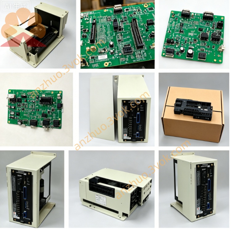
1. Product Overview
2. Core Functions
Central terminal junction for internal cabinet 24VDC power, safety interlock, analog signal and bus wiring between CPU board (PC-20), servo control board (N2-3) and analog output board (NEW02-2).
Concentrates emergency stop, safety door and external sensor wiring, standardizes cable routing inside the control cabinet.
Fixes and organizes harness connected to R10092-718 internal wiring harness, avoids messy wiring and intermittent poor contact.
3. Electrical & Environmental Specifications
Rated input voltage: DC24V / DC5V from cabinet internal power supply
Operating ambient temperature: 0℃ ~ +40℃; Storage temperature: -20℃ ~ +50℃
Working humidity: 10%~80% RH, non-condensing; Max applicable altitude ≤1000m
Mounting position: Installed beside the XRC rack backplane near PC-20 main CPU board
4. Typical Fault Manifestations
Random servo OFF alarms and intermittent axis runaway alerts caused by oxidized terminal pins or loose wiring contact.
Abnormal analog output from NEW02-2 module leading to welding proportional valve malfunction due to damaged signal terminals.
Frequent teach pendant communication errors triggered by aging terminal crimping of safety circuit lines.
5. Replacement & Safety Operation Guide
Cut off the total AC power supply of robot controller, wait no less than 15 minutes for residual voltage discharge; hot disassembly/swap is strictly prohibited.
Mark all terminal wiring numbers before removing the faulty RPN710-193A-6-10 component, install new/refurbished part and wire strictly per original labeling.
Restore full wiring connection, power on after installation, test single-axis jog motion, peripheral I/O signal and analog output function sequentially.
Get a Quote