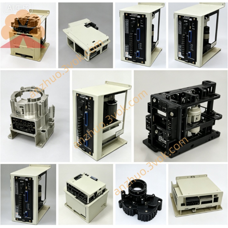
JANCD-YBK21-3E (DX200 Enhanced Brake Control Board)
Description
1. General Information
2. Specifications
Control Axes: Up to 12 axes (vs. 9 axes on YBK01)
Power Supply: DC 24 V ±10% (brake power input)
On-Board Fuse: F1 = 5 A / 250 V (higher than YBK01’s 3 A)
Max Output Current: Per axis ≤1.5 A (relay-driven, higher than YBK01)
Operating Temperature: 0 °C to +55 °C
Storage Temperature: -20 °C to +70 °C
Humidity: 30%–85% RH (non-condensing)
Dimensions (W×H×D): Approx. 154 × 284 × 30 mm
Weight: Approx. 0.85 kg
Mounting: Standard slot on JANCD-YBB01/YBB02 backplane
3. On-Board Connectors & Layout
CN400: Brake Output (12 axes) → Motor brake cables
CN402: Contactor Interlock Input → Safety interlock circuit
CN403: Brake Power Input → DC24V (brake supply)
CN404: External Power Switch → For brake power source selection
CN405: Brake Command Input → From main axis board (EAXA21)
F1: 5 A / 250 V fuse (brake circuit protection)
Relays: 12× high-reliability brake relays (one per axis)
LEDs (Front Edge):
PWR: DC24V power OK
BRK: Brake active (engaged)
FLT: Fault (overcurrent/short)
4. Safety Precautions
Disconnect main power before installation/removal; wait 15 minutes for capacitor discharge—electric shock hazard.
Never release brakes without mechanical support (axes will drop under gravity—crush hazard).
Do not connect/disconnect brake cables while power is ON.
Ensure low-resistance grounding (<0.1 Ω) for board and cabinet.
Keep away from water, oil mist, dust, and direct sunlight.
Replace only with JANCD-YBK21-3E; do not substitute YBK01 or other models.
Do not bend, drop, or over-tighten mounting screws—PCB cracking risk.
Clean only with a dry lint-free cloth; avoid contact with gold connectors.
5. Installation Procedure
Power OFF: Turn off controller main power; wait 15 minutes.
Cabinet Access: Open front door; locate vacant I/O slot on YBB01/YBB02 backplane.
Board Insertion:
Align YBK21-3E with slot guides.
Push firmly until fully seated (latch clicks into place).
Cable Connection:
CN400 → Motor brake cables (12 axes max).
CN403 → DC24V brake power supply.
CN405 → Brake command cable from EAXA21 axis board.
CN402 → Safety contactor interlock signal.
Close Cabinet: Secure front door; restore main power.
Verification: Check PWR LED (ON); test brake operation via teach pendant.
6. Replacement Instructions
Backup Data: Save all programs, parameters, and system data to CF card.
Power OFF: Disconnect main power; wait 15 minutes.
Disconnect Cables: Unplug CN400, CN402, CN403, CN404, CN405.
Remove Old Board: Release latch; pull board straight out (avoid twisting).
Install New Board: Follow Section 5 steps 3–4.
Reconnect Cables: Verify pin assignment matches labels.
Power ON & Test: Check LEDs; perform brake ON/OFF test for all axes.
7. Troubleshooting
Brakes Will Not Release
Check CN403 DC24V input (24V ±10%).
Verify F1 fuse continuity (5 A).
Confirm CN405 brake command signal from EAXA21.
Inspect CN400 cables for looseness or damage.
Brakes Will Not Engage (Axis Drifts)
Verify CN402 interlock signal is closed (safety circuit active).
Check for stuck relays on YBK21-3E.
Test brake coils for short circuits.
FLT LED ON (Fault)
Inspect brake wiring for short circuits (most common cause).
Check for overcurrent on any axis brake coil.
Replace YBK21-3E if internal relay damage is confirmed.
8. Maintenance
6-Month Inspection: Check connector tightness, fuse condition, and dust buildup.
Cleaning: Use dry lint-free cloth; avoid touching relay contacts.
Connector Care: Clean with contact cleaner if oxidation occurs.
Replacement Life: 5–8 years (or immediately if burned, corroded, or relays fail).
9. Compatibility
Fully Compatible: DX200 with YBB01/YBB02 backplanes.
Limited Compatibility: DX100/NX200 (requires firmware update and slot reconfiguration).
Not Compatible: YBK01 cannot replace YBK21-3E (axis count/current rating differences).
Get a Quote