JANCD-Y0P01
Description
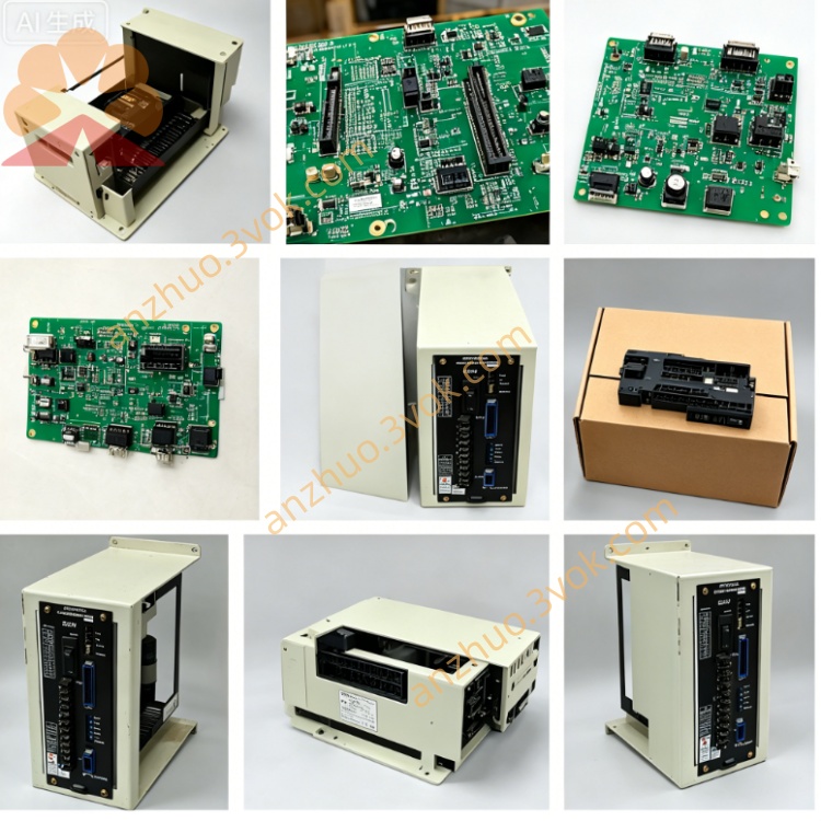
1. General Information
Model: JANCD-Y0P01 (also marked JANCD-Y0P01-E)
Manufacturer: Yaskawa Electric (Motoman Robotics)
Applicable Controller: DX100 / DX200 series robot controllers
Board Function: General-purpose option I/O & expansion board
Status: Active / available as original or refurbished
System Compatibility: Works with YCP01B-E (CPU), YIO01-E (I/O), YEW01-E (welding)
2. Specifications
Power Supply: 24 VDC ±10% (from controller internal power)
Current Consumption: Approx. 300 mA
Operating Temperature: 0 °C to +55 °C
Storage Temperature: -25 °C to +85 °C
Humidity: 5%–80% RH, non-condensing
Altitude: Up to 1,000 m (no derating)
Protection: Overvoltage, overcurrent, ESD protection
Dimensions (W×H×D): Approx. 120 × 160 × 25 mm
Weight: Approx. 200 g
3. Features & Functions
Expansion I/O: Provides 16 digital inputs / 16 digital outputs (NPN/PNP selectable).
Analog Interface: 2-channel analog input (0–10 VDC / 4–20 mA) for process sensors.
Communication:
Internal bus: To CPU board (YCP01B-E)
Serial: RS-232 port for external device connection
Application:
Peripheral control (conveyors, clamps, pneumatic units)
Analog sensor monitoring (pressure, temperature, voltage)
Custom I/O expansion for assembly, material handling, and packaging
4. Board Layout & Connectors
CN1: 24 VDC power & ground
CN2: Digital input terminal block (16 points)
CN3: Digital output terminal block (16 points)
CN4: Analog input (CH1 / CH2)
CN5: RS-232 communication port
SW1: I/O type selection (NPN / PNP)
LED Indicators:
PWR: Power ON
IN0–IN15: Input status
OUT0–OUT15: Output status
5. Installation & Wiring
Power Off: Turn off the DX controller and wait 5 minutes.
ESD Protection: Use anti-static wristband.
Slot Installation: Insert into dedicated option slot; secure with screws.
Internal Connection: Connect bus cable to CPU board.
External Wiring:
CN1: 24 VDC ±10% / GND
CN2/CN3: Field sensors / actuators (24 VDC)
CN4: Analog sensors (0–10 VDC or 4–20 mA)
CN5: RS-232 device (9600 bps, 8N1 default)
6. I/O Allocation (Default)
Inputs (0–15):
0–7: General-purpose
8: Emergency stop (optional)
9: Home switch
10–15: General-purpose
Outputs (0–15):
0–7: General-purpose
8: Servo enable
9: Alarm reset
10–15: General-purpose
7. Common Alarms & Troubleshooting
Alarm 5101: Option board communication error
Cause: Loose bus cable, faulty board, or CPU mismatch
Action: Re-seat cable; verify model compatibility
Alarm 5102: 24 VDC power fault
Cause: Short circuit, overload, or power supply failure
Action: Check wiring; reduce load; test power supply
Inputs not responding:
Cause: Wrong SW1 setting, loose connector, or sensor fault
Action: Verify NPN/PNP setting; check connections
Outputs not activating:
Cause: Overload, wiring fault, or output transistor damage
Action: Check load; test with multimeter
8. Maintenance & Replacement
Inspection: Check connectors annually for tightness and corrosion.
Cleaning: Use dry, soft cloth; avoid liquid cleaners.
Replacement: Use only JANCD-Y0P01 (no substitutes).
Warranty: New: 12 months; refurbished: 3–6 months.
9. Safety Precautions
Read manual before installation/operation.
Only qualified personnel may install, wire, or service.
Disconnect all power before maintenance.
Do not touch live circuits or hot components.
Use ESD protection to prevent static damage.
Get a Quote