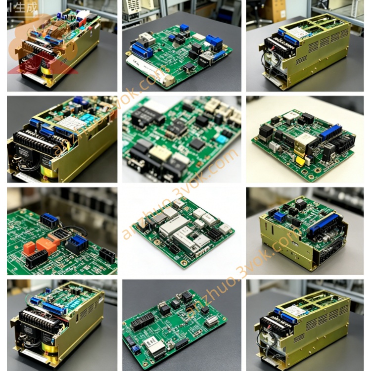
JANCD-XIO01
Description
1. Overview
Type: Robot controller I/O PCB (digital input/output)
Applicable controller: XRC1000, XRC2001
Position: Installs in the XRC controller’s I/O slot, connects to the CPU board (JANCD-XCP01 series)
Common variants: JANCD-XIO01B (revised version)
2. Specifications
Power supply: 24 VDC ±10%, approx. 10 W
Digital inputs: 16 channels (non-isolated, 0–30 VDC)
Digital outputs: 16 channels (non-isolated, transistor type, 24 VDC, 0.5 A/ch)
Communication: Onboard RS-485 (Modbus RTU) for I/O expansion
Operating temperature: -20 °C ~ +60 °C
Storage temperature: -40 °C ~ +85 °C
Humidity: ≤80% RH (non-condensing)
Dimensions: 120 × 50 × 30 mm
Weight: ~0.2 kg
3. Interface & Wiring
CN1: 24 VDC power & GND
CN2: 16 inputs (IN0–IN15, 24 VDC sink/source)
CN3: 16 outputs (OUT0–OUT15, NPN/PNP selectable)
CN4: RS-485 (Modbus RTU) for expansion I/O
CN5: Internal bus to CPU board
4. Functions
Signal acquisition: Reads digital signals from sensors, limit switches, push buttons
Output control: Drives relays, solenoids, indicators, and contactors
Interlocking: Safety interlocks and process signal handshaking with PLC
Expansion: RS-485 Modbus RTU connects remote I/O or HMI
5. Compatibility & Replacement
Fits: XRC1000, XRC2001 (XRC series only)
Replaces: Older JANCD-XIO02 (pin-compatible upgrade)
Not for: DX200 (uses JANCD-AIO01-E)
6. LED Indicators
PWR (green): 24 VDC OK
RUN (green): Board active, CPU communication normal
IN (yellow, 16×): Input channel status (ON = light)
OUT (yellow, 16×): Output channel status (ON = light)
ALM (red): I/O fault, overload, or bus error
7. Installation & Maintenance
Power off the controller and wait ≥5 minutes for capacitors to discharge.
Use anti-static wristband during handling.
Insert into the I/O slot, secure with 4 screws, and reconnect all cables.
Before replacement, back up CMOS and job data via CF card.
Periodically check terminals for looseness or damage.
8. Key Differences from XIO02
XIO01: 16-in/16-out, RS-485 Modbus, wide temperature -20~+60 °C
XIO02: 8-in/8-out, no serial, narrower temperature 0~+40 °C
Get a Quote