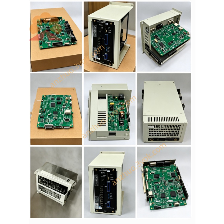
JANCD-X1002 (JANCD-X1O02) High‑Speed I/O & Motion Interface Board
Description
1. General Information
Model: JANCD-X1002 (commonly miswritten as JANCD-X1O02)
Manufacturer: Yaskawa Electric Corporation (Motoman Robotics)
Applicable Controller: DX100 Robot Controller
Function:
High‑speed digital input/output
Motion control signal interface
External axis synchronization
Safety interlock and E‑stop logic
Revision: REV.A, REV.B (drop‑in compatible)
2. Specifications
2.1 Electrical
Supply Voltage: 24 VDC ±10%
Current Consumption: ≤ 1.2 A
On‑board Fuse: 3 A (fast‑blow)
Digital Inputs: 32 × 24 VDC (NPN/PNP auto‑sense)
Digital Outputs: 16 × 24 VDC / 0.5 A (PNP transistor)
Isolation: Opto‑isolated, 2500 Vrms
2.2 Physical
Dimensions: 190 × 120 × 35 mm
Weight: Approx. 150 g
Mounting: DX100 option slot, 4 × M3 screws (0.8–1.0 N·m)
2.3 Environmental
Operating Temperature: 0 °C to +55 °C
Storage Temperature: −10 °C to +60 °C
Humidity: 5%–80% RH (non‑condensing)
Vibration: ≤ 0.5 G (10–500 Hz)
3. Connectors
- CN1 – Power1: +24 VDC2: 0 VDC (GND)3: FG (Frame Ground)
- CN2 – Digital Inputs (IN01–IN32)
IN01–IN16: Group 1 (common GND)
IN17–IN32: Group 2 (common GND)
- CN3 – Digital Outputs (OUT01–OUT16)
OUT01–OUT08: Group 1 (common +24 V)
OUT09–OUT16: Group 2 (common +24 V)
- CN4 – Safety & Sync1: E‑stop IN (NC)2: E‑stop GND3: Sync IN (external encoder)4: Sync OUT (to external axis)
4. LED Indicators
PWR (Green): On = 24 VDC normal
RUN (Green): Blinking = board active; Off = fault
ALM (Red): On = fuse blown / E‑stop open / overcurrent
COM (Yellow): Blinking = I/O communication active
5. Installation
Power OFF the controller; wait 5 minutes for capacitor discharge.
Use an anti‑static wristband.
Insert the board into the DX100 option slot; secure with 4 × M3 screws.
Connect CN1–CN4 according to the system wiring diagram.
Power ON and verify:
PWR = On
RUN = Blinking
ALM = Off
6. Safety Features
Overcurrent protection via 3 A fuse
E‑stop interlock compliant with Safety Category 3
Opto‑isolation to prevent ground loops
Fault signal (ALM) reported to DX100 controller
7. Maintenance & Troubleshooting
7.1 Maintenance
Quarterly: Check connectors and fuse.
Annually: Clean dust with low‑pressure air; inspect solder joints.
7.2 Troubleshooting
PWR Off: Check 24 VDC at CN1; verify wiring.
ALM On: Check 3 A fuse; test E‑stop continuity.
RUN Off: Re‑seat board; check for short circuits.
I/O No Response: Verify CN2/CN3 wiring; check LED status.
8. Compatibility
Replaces older boards: JANCD-X001, JANCD-X002
Compatible with standard/extended I/O of DX100
Applications: Welding, material handling, assembly, palletizing
9. Ordering Information
Part Number: JANCD-X1002 (specify revision: REV.A/REV.B)
Manufacturer: Yaskawa Electric Corporation
Warranty: 12 months under normal operating conditions
10. Warnings
For qualified personnel only.
Disconnect power before servicing; wait for discharge.
Do not modify the board; use only the specified fuse rating.
Yaskawa is not liable for improper use or installation.
Get a Quote