
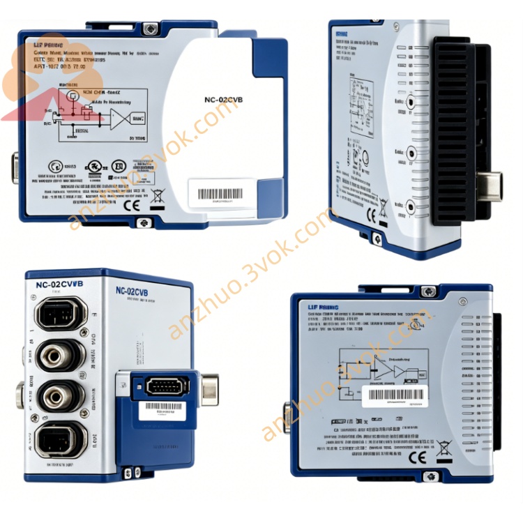
NI PXIe-5186 5GHz 12.5GS/s PXI High Speed Digitizer Oscilloscope
Description
Model Nomenclature
PXIe: PXI Express high-speed modular instrumentation bus.
51: NI PXI oscilloscope and digitizer series identifier.
86: Denotes the top-tier 8-bit module with 5 GHz bandwidth and 12.5 GS/s sampling rate, superseding the 3 GHz PXIe-5185NI.
Technical Specifications
Form Factor: 3U single-slot PXIe module.
Channels: 2 fully independent analog input channels.
Bandwidth: 5 GHz (50 Ω); 500 MHz (1 MΩ).
Sampling Rate: 12.5 GS/s (1 channel), 6.25 GS/s (2 channels); 250 GS/s random interleaved sampling (RIS) equivalent.
Resolution: 8-bit vertical resolution.
Input Impedance: Software-selectable 50 Ω or 1 MΩ.
Voltage Range (Full-Scale): 110 mVpp to 10 Vpp (50 Ω); up to 50 Vpp (1 MΩ).
Onboard Memory: 32 MB/channel (782058-01) or 1 GB/channel (782058-02).
Rise Time: ~70 ps (50 Ω, typical).
SFDR: >40 dBc (typical at 2 GHz).
Coupling: AC/DC software-selectable.
Filters: Programmable low-pass and high-pass filters.
Environmental: Operating 0 °C to 55 °C; Storage -40 °C to 70 °C.
Connectors: Front-panel BNC for CH0/CH1 analog inputs, REF CLK, CLK IN, and TRIG I/ONI.
Interface and Communication Configuration
Bus: PXIe Gen2 x4, up to 2 GB/s data streaming.
Drivers: NI-Scope, NI-DAQmx, IVI-COM for Windows.
Software Support: NI-MAX for configuration/diagnostics; LabVIEW, C/C++, Python, .NET for automation.
Synchronization: PXI trigger bus, star trigger, NI-TClk (picosecond-level alignment).
Clock: External 10 MHz reference input/output.
Data Transfer: DMA for continuous waveform streaming; multi-record acquisition (up to 100,000 segments).
Core Features
5 GHz Ultra-Wideband: Captures microwave, mmWave, and high-speed digital signals with minimal attenuation.
12.5 GS/s Real-Time Sampling: Resolves fast transient events and high-frequency harmonics accurately.
Dual Impedance Flexibility: 50 Ω for RF/microwave matching; 1 MΩ for general-purpose probing.
Deep Memory Options: 1 GB/channel enables long-duration acquisition without host intervention.
Advanced Triggering: Edge, pulse, window, video, pattern, and RF trigger for complex waveform stabilization.
Precision Synchronization: NI-TClk aligns multiple PXIe instruments for multi-channel and mixed-signal test.
Built-In Self-Calibration: Corrects DC drift and gain errors to maintain accuracy between external calibrations.
Application Scenarios
Aerospace & Defense: Radar pulse characterization, electronic warfare (EW) signal capture, satellite communication RF/IF testing.
High-Speed Digital: 100G/400G Ethernet, PCIe 6.0, DDR6 timing and signal integrity validation.
Semiconductor Test: High-speed I/O characterization, clock jitter analysis, power rail transient measurement.
Wireless Communication: 5G/6G massive MIMO, mmWave transceiver validation, wideband IF signal analysis.
Research & Development: Ultrafast laser, physics, and high-energy experiment signal acquisition.
Get a Quote