
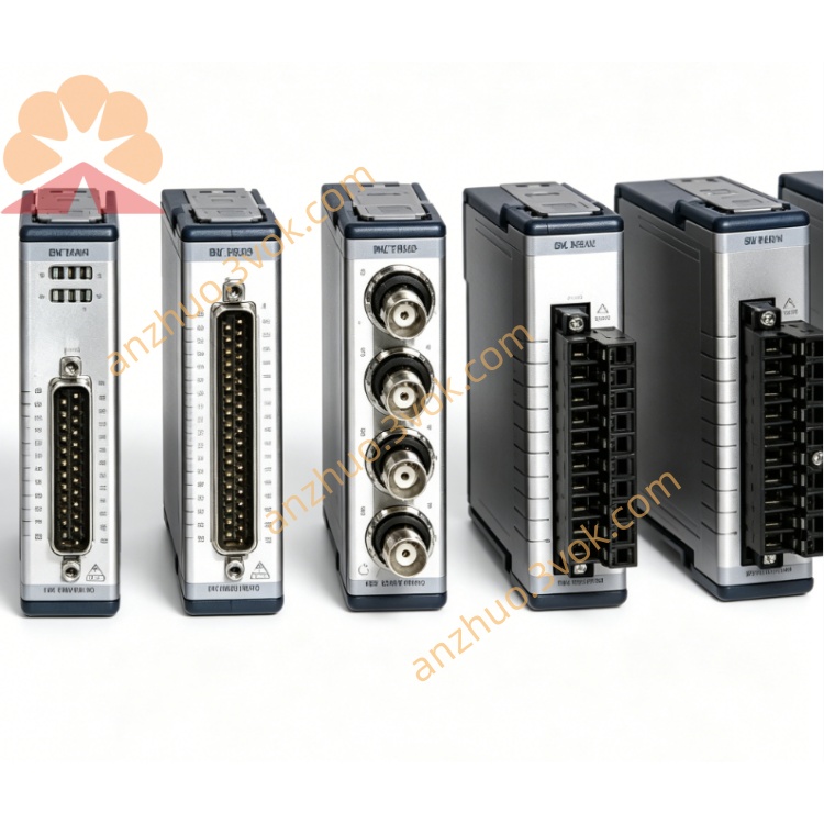
NI PXI-6713R 12Bit 8CH Analog Output PXI Module
Description
II. Model Interpretation
PXI: Standard 3U single slot, compatible with PXI/PXIe mixed slots, connects to the PXI trigger bus and backplane clock.
6713: 671x high-speed analog output series, 1 represents high-speed 1 MS/s, 3 represents 8-channel voltage output + digital I/O + counter integrated configuration NI.
Positioning: High-speed synchronous waveform generation and control module, suitable for multi-channel, high refresh rate, deterministic timing testing and control.
III. Technical Parameters (25℃)
1. Analog Output (AO)
Channels: 8 voltage outputs, synchronized update NI.
Resolution: 12 bits (4096 quantization levels) NI.
Output range: -10 V ~ +10 V (software programmable) NI.
Maximum update rate: 1 MS/s/channel, multi-channel synchronization without phase difference NI.
Accuracy: ±8.62 mV (full scale).
Drive capability: single channel 5 mA, total current 40 mA.
Bandwidth: 400 kHz (small signal).
2. Digital I/O
Channels: 8 5 V TTL/CMOS, bidirectional configurable NI.
Level: high ≥ 2.4 V, low ≤ 0.4 V, maximum charging / discharging current 8 mA.
3. Counter / Timer
Quantity: 2 24-bit, maximum 20 MHz NI.
Function: pulse generation, event counting, period / frequency measurement, PWM output NI.
4. Physical and Environmental
Connector: 68-pin SCSI-II (male).
Power supply: PXI backplane + 5 V/1.25 A, no external power supply required.
Operating temperature: 0 ℃ ~ 50 ℃.
Storage temperature: -20 ℃ ~ 70 ℃.
Power consumption: approximately 6.25 W.
IV. Interface and Communication Configuration
1. Hardware Interface
Front panel: 68-pin SCSI-II, includes 8 AO, 8 DIO, 2 counters, power / ground, suitable for shielded cables.
Back panel: connects to PXI_TRIG (6 channels), PXI_CLK10, supports multi-module synchronization and external clock input.
2. Software and Drivers
Driver: NI-DAQmx, supports waveform output, trigger configuration, counter programming, multi-card synchronization NI.
Development environment: LabVIEW, C/C++, Python, TestStand, supports DMA high-speed transmission NI.
Function: custom waveforms (sine / square / triangle / pulse / complex waveforms), hardware triggering, external clock locking NI.
V. Core Functions
8-channel 1 MS/s synchronous waveform output
Each channel is independently updated at 12 bits per channel at 1 MS/s, multi-channel synchronization deviation < 1 μs, can generate standard waveforms and custom complex waveforms NI.
Integrated digital I/O and counter, integrated control
8 channels of TTL I/O compatible with switch quantity control / status reading; 2 24-bit counters achieve precise timing, pulse generation and event counting, simplifying system architecture NI.
Hardware triggering and external clock synchronization
Supports software / hardware / external clock triggering, can lock PXI backplane clock or external reference, multi-module synchronization accuracy < 500 ns NI.
High-speed DMA transmission, low CPU usage
3 DMA channels, supports scatter-gather mode, low CPU usage when outputting large data waveforms.
Alternative to multiple types of instruments, reduces system cost Alternative to independent function generators, low-speed arbitrary waveform cards, and simple PID controllers, reducing the number of devices and the complexity of wiring. NI.
VI. Application Scenarios
High-speed excitation - response testing
Synchronously generate excitation signals in vibration, acoustic, and structural testing, and cooperate with acquisition cards to achieve closed-loop testing. NI.
Power and power control
Output of analog power supply, battery charging and discharging control, high-speed drive of heaters/motors, providing precise voltage/current settings. NI.
Sensor signal simulation
Simulate dynamic output of pressure, temperature, strain, and acceleration sensors to verify the accuracy and response of the acquisition system. NI.
Automated testing (ATE)
Circuit board and module function testing, simulation of analog/digital mixed signals, verification of DUT timing and functionality. NI.
High-speed deterministic control system
High-speed control of industrial processes, generation of motion control instructions, PWM output, timing determinism < 1 μs. NI.
VII. Installation and Maintenance Instructions
1. Installation and Power On
Disconnect power, insert into any slot of the PXI chassis, tighten screws and securely ground; before powering on, check that the 68-pin cable has no short circuit to avoid damaging the output channels. Keep the chassis ventilated during operation, with an environmental temperature ≤ 50°C to avoid temperature accumulation affecting accuracy.
2. Wiring and Operation
Cables: Use shielded 68-pin SCSI cables, separate analog and digital signals for wiring to reduce crosstalk; load resistance ≥ 1 kΩ to avoid overload.
Configuration: Set the output range, update rate, and waveform data in the software; when multiple cards are synchronized, use the PXI_TRIG signal to ensure consistent timing. NI.
Protection: Short-circuit output will trigger overcurrent protection, and the software can be configured for automatic fault shutdown to protect the module and load. NI.
3. Daily Maintenance
Regularly clean the 68-pin connectors, check the integrity of the cable shielding layer, add a dust cap when the equipment is idle for a long time, to prevent oxidation and dust from affecting contact reliability.
Calibration: Suggested once a year, use the NI-DAQmx calibration tool to calibrate output accuracy and linearity, and compensate for temperature drift. NI.
Driver Update: Regularly update the NI-DAQmx driver to fix compatibility issues and optimize waveform output stability. NI.
Get a Quote