
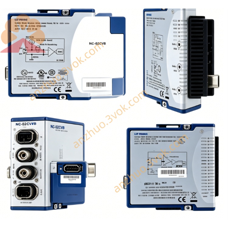
NI PXIe-4143 2-Channel High Precision Source Measure Unit
The PXIe-4143 is a four-channel four-quadrant precision Source Measure Unit delivered in a standard 3U single-slot PXI Express module. Each channel provides an output range of ±24 V and ±150 mA, with an ultra-high current sensitivity of 10 pA. It supports bidirectional power sourcing and sinking with a maximum power rating of 3.6 watts per channel. Combining extended voltage and current coverage with picoampere-level measurement accuracy, this module is well-suited for characterizing power semiconductors, low-leakage components and multi-channel integrated circuits. It is widely deployed in high-pin-count automated test systems and advanced precision measurement applications.
Description
Model Nomenclature
PXIe refers to the PXI Express high-speed modular instrumentation bus. The number 41 represents the product line of precision source measure units. 4143 stands for a four-channel SMU that features ±24 V and ±150 mA output range, 10 pA ultra-high current sensitivity and enhanced power handling capability.
Technical Specifications
This module adopts a 3U single-slot mechanical structure and integrates four fully independent channels. Each channel is isolated from chassis ground with 60 VDC CAT I isolation. The programmable voltage range is ±24 V, and the minimum voltage adjustment step is 0.1 millivolts. The current range spans ±150 mA, equipped with five automatic ranging current scales to adapt to different measurement levels. The maximum continuous power for each channel is 3.6 watts.
The module achieves 10 pA current sensitivity on the lowest current range. The simultaneous sampling rate for voltage and current measurement can reach up to 600 kS/s, and the signal update rate is up to 100 kS/s. In terms of electrical accuracy, the voltage error is within ±0.02 percent of the full range plus 50 microvolts, while the current error is within ±0.03 percent of the full range plus 10 pA on the minimum current scale. It supports four-wire remote sense with guard function and programmable output impedance. Built-in protective functions include overvoltage protection, overcurrent protection, reverse polarity protection and overtemperature protection.
The operating temperature ranges from 0 degrees Celsius to 55 degrees Celsius, and full rated accuracy is guaranteed between 18 degrees Celsius and 28 degrees Celsius. The storage temperature ranges from -40 degrees Celsius to 70 degrees Celsius. The working humidity is 10 percent to 70 percent without condensation. A 30-minute warm-up period is required before conducting high-precision tests. The recommended calibration cycle is one year. All external signal connections are implemented via a 25-pin male D-Sub connector.
Interface and Communication Configuration
The module applies the PXIe Gen1 bus and supports plug-and-play operation on Windows operating systems. Users can complete hardware configuration, parameter setting and device status diagnosis through NI-MAX. Interactive manual control is available via InstrumentStudio. For secondary development and automated control, it is compatible with mainstream programming environments including LabVIEW, LabWindows/CVI, C++ and Python, relying on the dedicated NI-DCPower driver.
It utilizes PXI trigger lines to realize hardware synchronization across multiple modules, and can work in tandem with other PXI instruments to build continuous and coordinated test sequences. All input and output signals are connected through the front-panel 25-pin D-Sub connector.
Core Features
It supports full four-quadrant operation, enabling both power sourcing and sinking to meet the test requirements of various active electronic devices. The 10 pA ultra-high current sensitivity allows accurate detection of extremely weak current signals and tiny leakage current. Equipped with SourceAdapt technology, the module can dynamically adjust transient response, effectively suppressing signal overshoot and maintaining stable output for different load conditions.
The four-wire remote sense design with guard terminal eliminates measurement errors caused by lead resistance and common-mode interference, ensuring reliable results in low-current and high-precision scenarios. High-speed sampling and updating performance support fast I-V curve sweeping and pulse testing. Multiple operation modes are provided to adapt to single-point measurement, continuous sequence testing and customized complex test procedures. Comprehensive protection mechanisms protect both the module and devices under test from damage caused by abnormal operating conditions.
Application Scenarios
It is used for parameter characterization and performance testing of power semiconductors such as MOSFETs, IGBTs and power diodes. It performs verification tests on power management chips, multi-channel system-on-chips and FPGAs within high-pin-count automated test equipment. It is ideal for measuring low-leakage electronic components, precision sensors and MEMS devices that demand ultra-low current detection capability.
The module can conduct charge and discharge cycle tests for medium-capacity batteries and supercapacitors. It is also applied to reliability and performance evaluation of avionics and defense electronic modules which require medium voltage, medium current and high measurement precision.
Usage and Maintenance Instructions
Installation and Configuration
Insert the module into a vacant 3U slot of the PXIe chassis and fasten the front panel latch. Connect test leads and sense wires to the 25-pin D-Sub connector, and properly wire the guard terminal when performing low-current measurements. Power on the chassis, and the system will automatically recognize the installed module. Launch NI-MAX to set voltage and current limits, enable remote sense function and configure trigger parameters. Develop corresponding test programs to realize automated testing, data acquisition and result analysis.
Daily Maintenance
Place the PXI chassis and module in a clean, dry and well-ventilated environment, and keep the ambient temperature within the rated range. Do not apply excessive force when plugging and unplugging connectors to avoid damaging internal pins. Regularly inspect connecting cables and connectors for dirt, aging or poor contact. Ensure sufficient airflow around the module during long-duration continuous operation. When the module is not in use, cut off the power supply, disconnect all cables, and store it in a dry place with electrostatic protection.
Safety Notice
Never operate the module beyond its rated voltage, current and power specifications to prevent permanent damage to internal circuits. Follow standard electrostatic protection procedures during handling, installation and operation. Disconnect all power supplies of the chassis before installing, removing or maintaining the module. Perform regular calibration in accordance with the recommended cycle to sustain long-term measurement accuracy. Dispose of the module in compliance with local electronic waste regulations when it reaches the end of its service life.
Get a Quote