
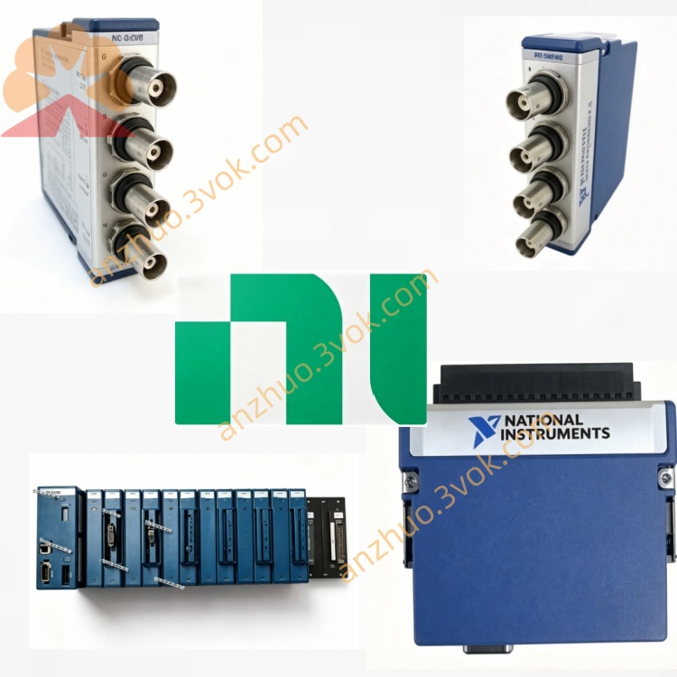
NI PXIe-4112 2CH 60V 1A Isolated Programmable DC Power Supply
Description
Model Nomenclature
Technical Specifications
Basic Parameters
Form Factor: 3U single‑slot PXIe module
Channels: 2 isolated channels (isolated from each other and chassis ground)
Voltage Range: 0.1 V to 60 V (minimum programmable step 0.1 V)
Current Range: 0.01 A to 1 A (minimum programmable step 0.01 A)
Power per Channel: 60 W; Total Module Power: 120 W
Readback Rate: Up to 5 kS/s (voltage and current)
Switching Time: Rise time <20 ms (full load), fall time <20 ms (full load)
Electrical & Protection
Load Regulation: 12 mV per ampere load change
Remote Sense: 4‑wire to compensate wiring losses
Output Disconnect: Relays for high‑impedance isolation
Protection: Overvoltage, overcurrent, inverse voltage, overtemperature
Environmental & Mechanical
Operating Temperature: 0 °C to 55 °C
Storage Temperature: -20 °C to 70 °C
Calibration Interval: Recommended every 2 years
Connectors: Phoenix Contact 5.08 mm (10‑position) for outputs; Weidmuller 3.5 mm for auxiliary power
Interface and Communication Configuration
Bus: PXIe Gen1, plug‑and‑play for Windows
Control Software: NI‑MAX for configuration; InstrumentStudio for interactive controlNI
Programming Environments: LabVIEW, LabWindows/CVI, C++, Python via NI‑DCPower driverNI
Triggering: PXI trigger lines 0–7 for hardware synchronization
Channel Linking: Series/parallel combining for higher voltage (120 V) or current (2 A)
Core Features
Isolated Outputs: Two fully isolated channels eliminate ground loops and improve safety.
High Accuracy: Precision programming and readback with 4‑wire remote sense ensure tight regulation.
Flexible Channel Combining: Channels can be series‑connected for 120 V at 1 A or parallel‑connected for 60 V at 2 A.
Integrated Protection: Comprehensive safeguards prevent damage from faulty DUTs or miswiring.
Fast Sequencing: Hardware timing and PXI triggering enable synchronized, high‑speed test sequences.
Application Scenarios
Automotive Electronics: Powering ECUs, sensors, and infotainment systems during validation and production test.
Aerospace & Defense: Providing stable power for avionics, radar, and communication modules in rugged environments.
Semiconductor & Component Test: Characterizing power ICs, transistors, and passive components with precise voltage/current sourcing.
Automated Test Systems: Integrating into PXI‑based ATE for high‑volume manufacturing test of wireless devices, medical equipment, and industrial controls.
Get a Quote