
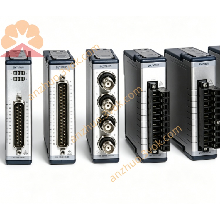
NI PXI‑5142 100MHz 100MS/s 14‑Bit PXI Oscilloscope
Description
Model Explanation
PXI: Standard 3U PXI hybrid bus module, single slot, compatible with PXI/PXIe chassis.
5142: NI 5100 series number, representing 2 channels, 100 MHz bandwidth, 100 MS/s, 14 bits, with onboard signal processing for PXI oscilloscope.
Component Number (by memory):
779587‑01: Standard memory for each channel
779587‑02: 256 MB for each channel
Technical Specifications (25℃, preheated for 15 minutes)
Channels: 2 analog inputs, full-channel synchronous sampling
Resolution: 14 bits
Sampling Rate: Real-time 100 MS/s; Board I/Q extraction can reduce the rate
Analog Bandwidth: 100 MHz (‑3 dB) NI
Input Voltage Range: ±100 mV to ±10 V (multiple levels, 200 mVpp to 20 Vpp) NI
Input Impedance: 50 Ω ±2% / 1 MΩ ±0.75% (software selectable) NI
Coupling Mode: AC/DC (per channel independently; AC only 1 MΩ effective)
Onboard Memory: Standard / 256 MB (per channel)
Spurious Free Dynamic Range SFDR: Typical 75 dBc (50 Ω, small signal) NI
Signal-to-Noise Ratio SNR: Typical 64 dB
Total Harmonic Distortion THD: <‑75 dBc (50 Ω, 10 MHz) NI
Triggering Mode: Edge, Window, Hysteresis, Digital Trigger; 100 ps timestamp; Pre-trigger / Post-trigger
Clock: Internal 100 MHz; External 4–100 MHz sampling clock; Lockable PXI 10 MHz reference
Onboard Signal Processing: Quadrature Digital Down Conversion (DDC), Baseband I/Q Extraction, Anti-aliasing Filter NI
Power Consumption: Approximately 19 W
Size / Weight: 3U single slot, approximately 480 g
Environment: Operating 0–55℃; Storage -40–70℃; Humidity 10%–90% RH (no condensation)
Interfaces and Communication Configuration
Front-end Interface
2×BNC: CH0–CH1 analog input
1×BNC (TRIG): External analog trigger input
1×SMB (CLK IN): External sampling clock / reference input
1×SMB (CLK OUT): Internal clock / reference output
1×9-pin mini DIN (AUX I/O): Digital trigger I/O, PFI0/PFI1
Panel Indicator Lights
PWR (green): Power normal
RUN (green): Active when collecting, flashes when waiting for trigger
ERR (red): Over-temperature, over-current or configuration error
Bus and Synchronization
PXI Hybrid Bus, supports PXI trigger bus, Star trigger, RTSI synchronization
Multi-module synchronization phase error < 1 μs, supports multi-channel phase coherent acquisition
Software Driver
NI‑SCOPE Driver, supports LabVIEW, TestStand, Python, C#
NI MAX: Device identification, self-check, configuration, calibration
Companion: Soft front panel SFP, built-in measurement functions, RF/communication signal processing library Core function
14-bit high-resolution low-noise acquisition: high quantization accuracy, low noise, suitable for small signals and high-precision measurements
100 MHz bandwidth + 100 MS/s sampling: covers medium and high-frequency signals, suitable for communication, ultrasound, radio frequency and other scenarios
On-board orthogonal DDC and I/Q extraction: real-time down-conversion and downsampling, reducing CPU load, optimizing baseband analysis
Wide dynamic range: 75 dBc SFDR, 64 dB SNR, effectively suppressing harmonics and noise
Flexible input configuration: each channel AC/DC coupling, 50 Ω/1 MΩ impedance, multiple voltage range options available
Precise triggering and timestamp: multiple triggering modes, 100 ps timestamp, accurately capturing transient events
PXI synchronization and streaming: multi-module synchronization, supports high-speed data streaming storage and long-record acquisition Applicable scenarios
Communication and RF testing: Baseband I/Q signals, modulation signals, receiver performance tests (EVM, MER) after RF down-conversion, NI
Wireless device development: Time-domain / frequency-domain analysis of short-range communication devices such as WiFi, Bluetooth, ZigBee
Audio and acoustics: High-fidelity audio, microphone / speaker testing, low distortion analysis
Industrial precision measurement: Power supply ripple, sensor signals, transient and steady-state analysis of precise circuits
Research and medical: Low-noise high-resolution acquisition of biological electrical signals, ultrasound imaging, mass spectrometry analysis, etc.
Automotive electronics: High-precision testing of vehicle sensors, ECU, vehicle network signals
User and maintenance instructions
Installation and power-on
Power off installation, insert single slot and fix; chassis reliable grounding for anti-static
Power-on preheating for 15 minutes, NI MAX self-check to confirm no hardware errors
Keep the chassis ventilated during operation, environmental temperature ≤ 55℃, avoid blocking fans
Wiring and operation
Use 50 Ω coaxial cable for high-frequency signals, tighten BNC connector to reduce signal reflection
Select 50 Ω impedance for high-frequency / RF signals, 1 MΩ for low-frequency / high-voltage signals
Use AC coupling for small AC signals (only 1 MΩ), DC / slow-changing signals use DC coupling
Prioritize channel internal signals as trigger sources, set appropriate trigger level to avoid false triggering
Use PXI trigger bus or Star trigger for multi-module synchronization to ensure phase consistency
Maintenance and calibration
It is recommended to perform NIST traceable calibration once every 2 years; use internal self-calibration to compensate for temperature drift on a daily basis
Regularly clean dust from BNC/SMB/DIN interfaces to keep them dry; add dust caps for long-term inactivity
The working environment should be free of condensation, with humidity ranging from 10% to 90% RH, and away from strong electromagnetic interference
Do not input >±15 V voltage; do not plug in or unplug cables while powered on; avoid severe vibrations
Get a Quote