
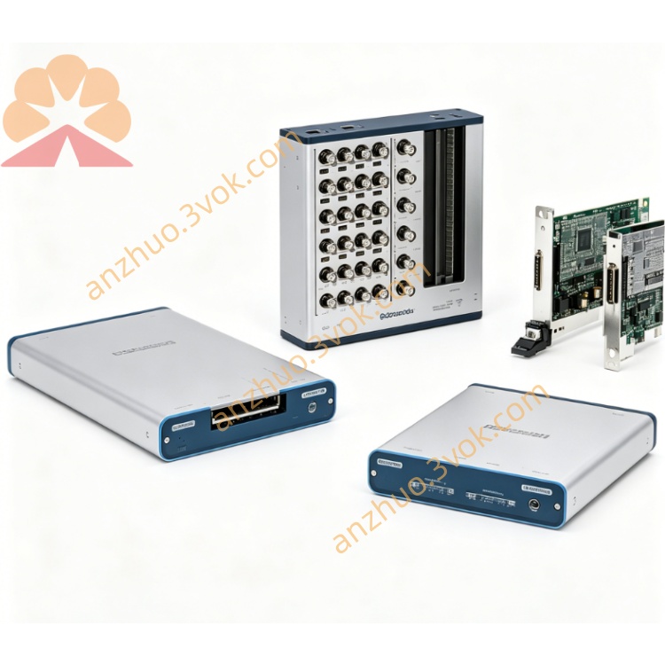
NI PXI‑5124 150MHz 200MS/s 12‑Bit PXI Oscilloscope
Description
Model Explanation
PXI: Standard 3U PXI hybrid bus module, single slot, compatible with PXI/PXIe chassis.
5124: NI 5100 series number, representing 2 channels, 150 MHz bandwidth, 200 MS/s, 12-bit, high-resolution PXI oscilloscope NI.
Component Number (by memory):
778757‑01: 8 MB / channel
778757‑02: 32 MB / channel
778757‑03: 256 MB / channel
778757‑04: 512 MB / channel
Technical Parameters (25℃, preheating 15 min):
Channels: 2 analog inputs, full channel synchronous sampling NI.
Resolution: 12 bits NI.
Sampling Rate: Real-time 200 MS/s; Random interleaved equivalent up to 4 GS/s.
Analog Bandwidth: 150 MHz (‑3 dB) NI.
Input Voltage Range: 200 mVpp to 20 Vpp (multiple selectable levels).
Input Impedance: 50 Ω ±2% / 1 MΩ ±0.75% (software selectable) NI.
Coupling Mode: AC / DC / GND (per channel independent) NI.
Onboard Memory: 8 MB / 32 MB / 256 MB / 512 MB (per channel).
Spurious Free Dynamic Range SFDR: Typical > 75 dBc.
Triggering Method: Edge, Window, Hold, Video, Digital Trigger; 100 ps timestamp; Pre-trigger / Post-trigger.
Clock: Internal 200 MHz; External 4–200 MHz sampling clock; Lockable PXI 10 MHz reference.
Power Consumption: Approximately 20 W.
Size / Weight: 3U single slot, approximately 480 g.
Environment: Operating 0–55℃; Storage –40–70℃; Humidity 10%–90% RH (no condensation).
Interface and Communication Configuration
Front-end Interface NI:
2×BNC: CH0–CH1 analog input.
1×BNC (TRIG): External analog trigger input.
1×SMB (CLK IN): External sampling clock / reference input.
1×SMB (CLK OUT): Internal clock / reference output.
1×9-pin mini DIN (AUX I/O): Digital trigger I/O, PFI0/PFI1.
Panel Indicator Lights:
PWR (green): Power normal.
RUN (green): Active when collecting, flashes when waiting for trigger.
ERR (red): Over-temperature, over-current or configuration error.
Bus and Synchronization:
PXI hybrid bus, supports PXI trigger bus, Star trigger, RTSI synchronization.
Multi-module synchronization phase error < 1 μs, scalable multi-channel synchronization acquisition.
Software Driver:
NI‑SCOPE driver, supports LabVIEW, TestStand, Python, C#.
NI MAX: Device identification, self-check, configuration, calibration.
Companion: Soft front panel SFP, built-in measurement functions, signal processing library. Core function
12-bit high-resolution + 200 MS/s high-speed acquisition: Balances accuracy and speed, precisely capturing mid-high frequency transient signals. NI.
150 MHz bandwidth input: Covers mid-high frequency signals, suitable for communication, ultrasound, radio frequency and other tests.
Extremely large deep storage: Up to 512 MB per channel, supports long-term waveform recording and multi-segment acquisition.
Flexible input configuration: Each channel can be AC/DC/GND coupled, with 50 Ω/1 MΩ impedance, and multiple voltage range options available. NI.
Precise triggering and timestamp: Multiple triggering modes, 100 ps timestamp, precisely capturing transient events.
Wide dynamic range: >75 dBc SFDR, effectively suppressing harmonics and noise, improving measurement signal-to-noise ratio.
Multi-module synchronous expansion: PXI/RTSI/Star trigger synchronization, builds a phase coherent acquisition system. Applicable scenarios
Communication and Radio Frequency: Time-domain / Frequency-domain analysis of baseband signals, modulation signals, and low-noise RF signals.
Ultrasound and Non-destructive Testing: High-speed and high-precision acquisition of ultrasonic echo signals and imaging signals.
Automotive Electronics: High-speed sensor signals, ECU waveforms, and vehicle network signal testing.
Audio and Acoustics: High-fidelity waveforms and distortion analysis of microphones, speakers, and audio equipment.
Research and Medical: Low-noise high-resolution acquisition of biological electrical signals, ultrasound imaging, mass spectrometry analysis, etc.
Industrial Precision Measurement: Power supply ripple, sensor signals, and transient and steady-state analysis of precise circuits.
User and Maintenance Instructions
Installation and Power On
Power off installation, insert into single slot and fix; the chassis is reliably grounded to prevent static electricity.
Power on preheating for 15 minutes, NI MAX self-check to confirm no hardware errors.
Keep the chassis ventilated during operation, environmental temperature ≤ 55℃, avoid blocking the fan.
Wiring and Operation
Use 50 Ω coaxial cable for high-frequency signals, tighten the BNC connector to reduce signal reflection NI.
Select 50 Ω impedance for high-frequency / RF signals, 1 MΩ for low-frequency / high-voltage signals NI.
Use AC coupling for AC small signals, DC / slow-changing signals use DC coupling NI.
Prioritize selecting signals within the channel as trigger sources, set appropriate trigger levels to avoid false triggering.
Use PXI trigger bus or Star trigger for multi-module synchronization to ensure phase consistency.
Maintenance and Calibration
It is recommended to perform NIST traceable calibration once every 2 years; use internal self-calibration to compensate for temperature drift on a daily basis.
Regularly clean dust from BNC/SMB/DIN interfaces to keep them dry; add a dust cap when the equipment is idle for a long time.
The working environment should be free of condensation, with a humidity of 10%–90% RH, and away from strong electromagnetic interference.
Do not input >±20 V voltage; do not plug in or unplug cables while powered on; avoid severe vibrations.
Get a Quote