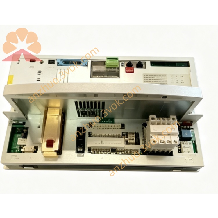
KUKA 20-REL Robot Digital Output Relay Module For KRC Controller Cabinet
Description
Model: KPS‑600/20‑REL
Order No.: 00‑110‑728
Application: KRC2 cabinets for KR150 to KR300 robots
Safety Type: Relay‑based (external safety relays)
2. Technical Specifications
Electrical
Input: 3∼ AC 400 V / 480 V (±10 %), 50/60 Hz
Rated current: 25 A (rms)
Peak current: 95 A (rms, 0.5 s)
DC Intermediate Circuit: 565–585 V DC
Rated: 20 A continuous
Peak: 64 A
Control Output: 24 V DC / 27 V DC, 30 A max
Power Rating: Approx. 12 kW
Protection: Overvoltage, undervoltage, overcurrent, short circuit, overtemperature, ground fault
Mechanical & Environmental
Dimensions (W × H × D): 200 × 120 × 100 mm
Weight: 4.7 kg
Protection Class: IP20 (cabinet installation)
Operating Temperature: 0 °C to +55 °C
Storage Temperature: −20 °C to +70 °C
Cooling: Integrated forced‑air fan; ≥50 mm clearance required
Safety (REL)
Safety Integrity: SIL1 / PLc (EN ISO 13849)
STO Response Time: 20–50 ms (relay contact delay)
Monitored Signals: E‑stop, safety doors (via external safety relays)
3. Connector Assignment (X1–X5)
X1 – Mains Input
L1, L2, L3: Three‑phase AC
N: Neutral
PE: Protective earth
X2 – DC Intermediate Circuit
DC+: 585 V DC positive
DC−: 585 V DC negative
Connects to X1 of all KSD1 servo drives
X3 – Control Voltage
+24 V / 0 V: Control power for cabinet components
X4 – Battery & Brake
BAT+, BAT−: Battery charging (2 × 12 V lead‑acid)
BRK+, BRK−: External brake resistor
X5 – Servo Bus & Safety
IBS IN / OUT: Interbus servo bus (to KSD1 drives)
SAFE: Relay‑based safety I/O (E‑stop/safety door contacts)
4. LED Status Indicators (Front Panel)
LED1 (Red) – Fault
Off: Normal operation
On: Critical fault (overvoltage, overtemperature, internal failure)
Flashing 3 Hz: Brake error
Flashing 6 Hz: Safety trip (E‑stop/safety door open, relay contact open)
LED2 (Green) – Power OK
Off: No power / processor inactive
Flashing 1.5 Hz: DC bus <60 V
On: DC bus >60 V (ready for operation)
5. Safety Instructions
High Voltage Hazard: DC intermediate circuit up to 585 V.
→ Wait at least 5 minutes after switching off for capacitors to discharge before maintenance.
Only qualified personnel may install or service this unit.
REL Wiring: External safety relays must be wired dual‑channel for E‑stop/safety doors.
Do not open, modify, or bypass internal components or safety relay circuits.
Ensure reliable PE connection for cabinet, KPS, and all drives.
Keep ventilation slots free; inadequate cooling causes overheating.
6. Installation & Wiring
Mount vertically in designated KRC2 cabinet slot.
Connect X1 to three‑phase mains (check phase sequence and PE).
Wire X2 (DC+/DC−) to DC bus distribution rail (KSD1 X1).
Connect X3 to 24 V DC control distribution.
Attach battery cables to X4 (BAT+/BAT−) and brake resistor to BRK+/BRK−.
Connect X5 IBS IN/OUT in daisy‑chain with KSD1 drives; wire safety relay contacts to SAFE (dual‑channel).
Tighten power terminals to 2.5 Nm.
7. Operation
Power‑On: Mains ON → internal charging → DC bus energizes.
Standby: Green LED2 ON (DC bus ready); red LED1 OFF (no faults).
Drive Operation: Supplies stable 585 V DC to KSD1 drives during motion.
Regenerative Energy: Dissipated via brake resistor (monitored by KPS).
Safety Stop: On E‑stop/safety door open → external safety relays open → STO activates → DC bus cut (20–50 ms delay) → red LED1 flashes 6 Hz.
8. Maintenance
Daily: Check LED status, fan operation, cable integrity.
Weekly: Clean fan and vents; remove dust.
Monthly: Retighten X1/X2/X4 power terminals (2.5 Nm).
Quarterly: Verify battery charging voltage and brake resistor resistance.
Annual: Inspect capacitors (bulging), fan wear, safety relay contact condition.
9. Common REL Faults & Troubleshooting
LED1 Flashing 6 Hz: Safety trip → check E‑stop, safety door, or external safety relay wiring/contacts.
LED2 Flashing 1.5 Hz: DC bus <60 V → check mains, cabinet fuses, or KPS internal fuse.
LED1 On (Overvoltage): Mains too high, regenerative overload, or brake resistor missing/faulty.
LED1 Flashing 3 Hz: Brake error → check BRK wiring or resistor.
Overtemperature: Fan blocked, vents covered, or ambient >55 °C.
Get a Quote