KUKA KSD1-64 Servo Drive Module For KRC2 Industrial Robot Controller Cabinet
Description
Order numbers: 00‑117‑345, 00‑105‑414
Application: KR150, KR210, KR240, KR300 and similar heavy‑payload robots
Control principle: Field‑oriented vector control (torque / speed / position loop)
Construction: Vertical cabinet mounting, hot‑swap capable, IP20 protection
2. Technical Specifications
Electrical Data
Intermediate circuit voltage: DC 0–585 V (24.5 A rated)
Output voltage: 3∼ AC 0–480 V, 0–480 Hz
Rated output current: 20 A
Peak output current: 64 A
Rated power: Approx. 32–40 kW (depends on DC bus voltage)
PWM frequency: 4 kHz / 8 kHz (configurable)
Control modes: Torque control, speed control, position control
Encoder support: EnDat 2.2 / resolver (motor‑feedback)
Mechanical & Environmental
Dimensions (W × H × D): 264 × 240 × 180 mm
Weight: Approx. 6.8 kg
Protection class: IP20 (for installation inside control cabinets)
Operating temperature: 0 °C to +40 °C
Storage temperature: −20 °C to +70 °C
Cooling: Forced air cooling (two high‑speed fans); maintain ≥50 mm clearance above and below for airflow
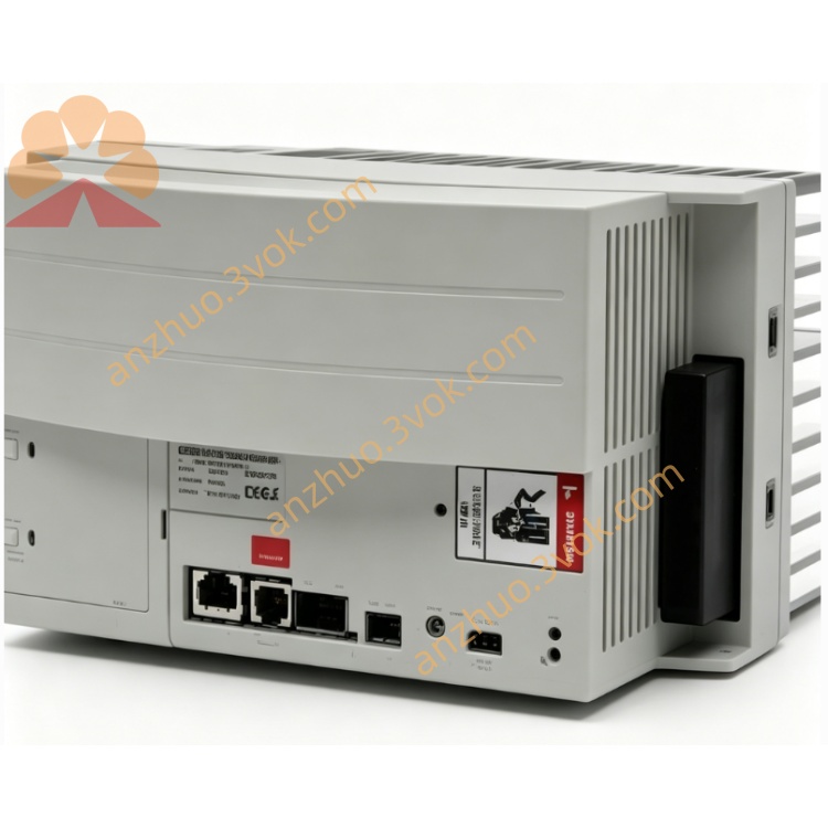
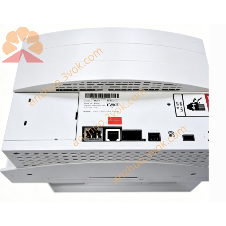
3. Connector & Interface Definition
X1 – Power & Control
DC intermediate circuit voltage (585 V DC)
24 V DC control supply
Status LEDs: green = Power OK, red = Fault
X2 – Motor Connection
3∼ motor power (U, V, W)
Motor brake connection
Encoder / resolver interface (EnDat / resolver)
KSD1-64: Dual‑connector design for high‑current wiring
X11 – Safety & Digital I/O
Safety signals: E‑stop, safety door interlock
24 V digital inputs / outputs
Safety level: EN ISO 13849‑1 Cat. 4
X13 / X14 – Servo Bus
X13 IN: Servo bus input (from controller or previous drive)
X14 OUT: Servo bus output (to next drive in daisy chain)
Bus type: Interbus (KUKA internal servo bus)
4. Main Features
Heavy‑duty performance: 64 A peak current for high‑torque motors
High dynamics: Fast torque response, precise positioning (±0.01°)
Full protection: Overcurrent, overload, overvoltage, undervoltage, overtemperature, short circuit, ground fault, motor temperature monitoring
Motor compatibility: KUKA permanent‑magnet synchronous motors (heavy‑duty series)
System compatibility: Works with KSS robot software; parameters configurable via KCP teach pendant or WorkVisual
Diagnostics: LED status + detailed fault codes in KCP / WorkVisual
5. Safety Instructions
High voltage hazard: Intermediate circuit DC voltage up to 585 V.
→ After switching off the controller, wait at least 5 minutes for capacitors to discharge before wiring or maintenance.
Do not open, modify, or bypass internal components or safety circuits.
Keep ventilation slots free of dust and obstructions.
Connect all safety interlocks correctly; never bypass safety loops.
Ensure reliable protective earth (PE) connection for cabinet, drive, and motor.
6. Installation & Wiring
Mount the drive vertically in a KRC2 cabinet slot.
Connect X1 to DC intermediate circuit and 24 V control power (observe polarity).
Wire X2 to motor power, brake, and encoder cables; use shielded cables with proper grounding.
Servo bus: X13 IN ← controller / previous drive; X14 OUT → next drive.
Connect X11 safety and I/O signals with twisted‑pair cables.
Tighten all power terminals to the specified torque.
7. Operation
Power‑on: After controller start‑up, DC bus voltage rises automatically.
Standby: Green LED ON, red LED OFF → drive ready.
Manual mode (T1/T2): Enable permit switch; jog axes via KCP.
Automatic mode: Drive follows robot program (PTP / LIN / CIRC motions).
Fault reaction: Red LED ON, drive disables output. Read fault code via KCP / WorkVisual for troubleshooting.
Get a Quote