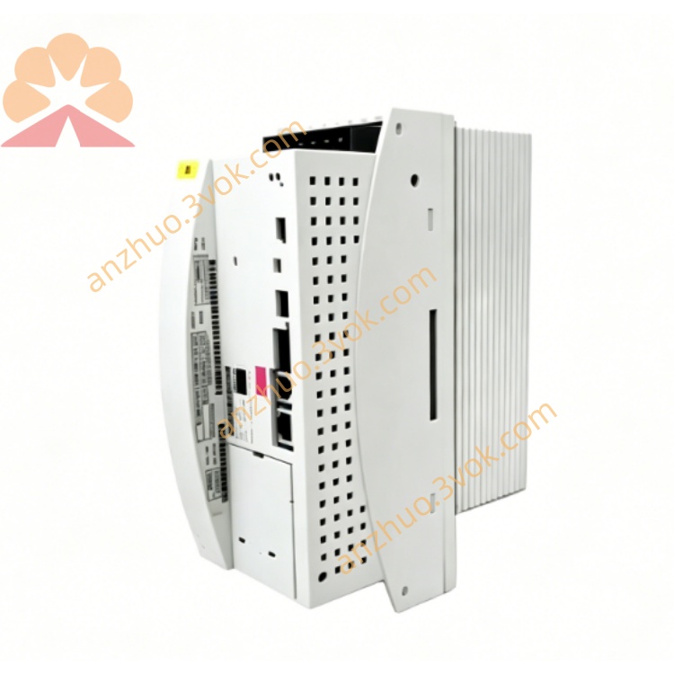
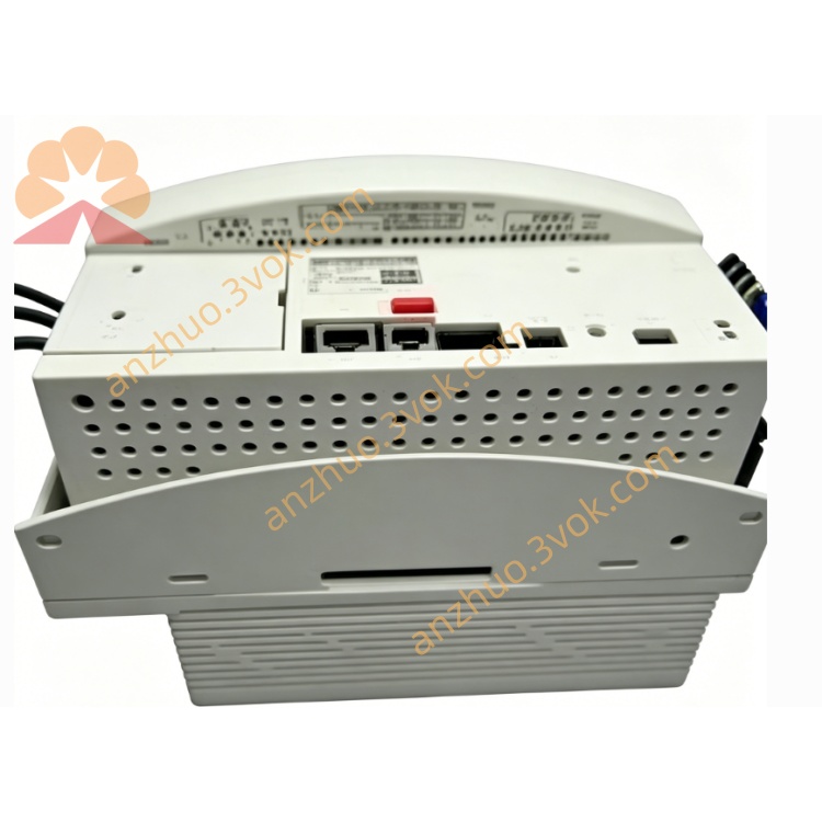
KUKA KSD1-16 Servo Drive Amplifier Module For KRC2 Industrial Robot Controller
Description
2. Technical Specifications
Model: KSD1-16 (Part No. 00-122-285)
Type: 3‑phase servo amplifier, 16 A (rated) / 32 A (peak)
Input: DC 0–770 V (intermediate circuit), 9.8 A
Output: 3‑phase AC 0–480 V, 8 A (rated) / 16 A (max), 0–480 Hz
Control Method: Field‑oriented vector control (torque/current/position)
PWM Frequency: 4 kHz / 8 kHz
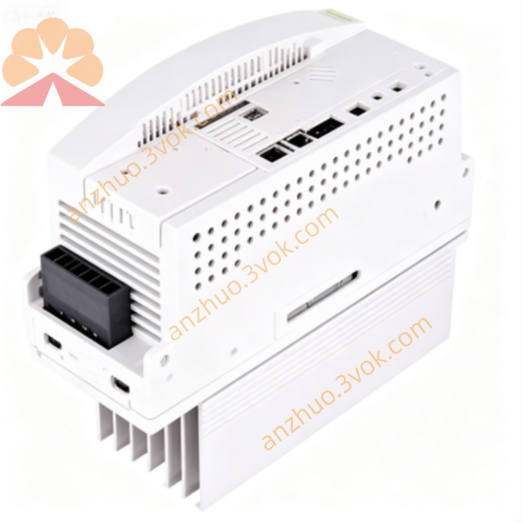
Cooling: Forced air cooling (integrated fan)
Protection: Overload, short‑circuit, overvoltage, undervoltage, overheating, encoder fault
Degree of Protection: IP20 (cabinet installation)
Operating Temperature: 0°C to +40°C
Storage Temperature: -20°C to +70°C
Dimensions (W×H×D): 132 × 240 × 180 mm
Weight: Approx. 3.2 kg (7.05 lbs)
Mounting: DIN rail or panel mount (vertical orientation)
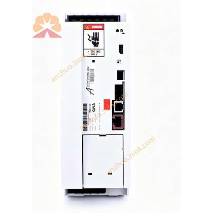
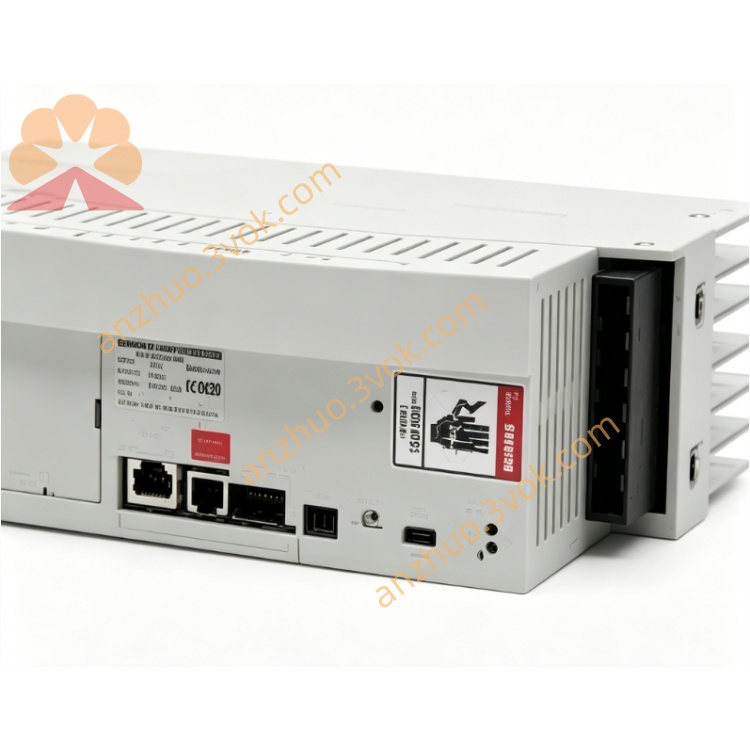
3. Interface & Connector Allocation
X1: Intermediate circuit (DC 0–770 V) + 24 V DC supply; green (Power) / red (Fault) LEDs
X2: Motor connection (3‑phase AC + brake + encoder)
X11: Automation interface (digital I/O, safety signals: E‑Stop, door interlocks)
X13: Servo bus IN (Interbus, daisy‑chain from controller/previous drive)
X14: Servo bus OUT (to next drive in chain)
4. Main Features
High Precision: Vector control for accurate torque/position control (±0.01°)
High Dynamics: 32 A peak current for fast acceleration/deceleration
Integrated Safety: Dual‑channel safety (EN ISO 13849‑1 Cat. 4) via X11
Drive Monitoring: Real‑time current/voltage/temperature/encoder monitoring
Compact Design: 132 mm width for space‑saving cabinet integration
Easy Configuration: Parameters via KUKA WorkVisual or teach pendant (KCP2)
5. Safety Instructions
High Voltage: DC 770 V and AC 480 V; disconnect power and wait ≥5 minutes for capacitors to discharge before servicing.
No Modification: Do not bypass safety circuits (E‑Stop, overvoltage, overheating).
Cooling: Keep ventilation slots unobstructed; maintain 50 mm clearance for airflow.
Work Envelope: Stay clear of moving axes during operation.
6. Installation & Wiring
Mounting: Attach vertically to DIN rail/panel; allow 50 mm clearance top/bottom for cooling.
DC Power (X1): Connect intermediate circuit (DC 0–770 V) from KPS power supply; observe polarity (+/−); torque to 1.2 Nm.
Motor (X2): Connect 3‑phase motor, brake, and encoder; shield cable per EMC guidelines; tighten connectors.
Servo Bus: Link X13 (IN) to controller/KSD1-08; X14 (OUT) to next drive (e.g., KSD1-32).
I/O/Safety (X11): Connect E‑Stop, safety doors, and 24 V DC I/O; use twisted‑pair cables.
Grounding: Earth drive, motor, and cabinet per local codes; ensure low‑resistance ground path.
7. Operation
7.1 Power‑Up
Verify all connections are secure.
Apply 3‑phase AC to KRC2 controller; intermediate circuit charges to 770 V DC.
Check X1 LEDs: Power (green) ON, Fault (red) OFF.
Enable drive via teach pendant (KCP2); Servo Ready (yellow) LED ON.
7.2 Normal Operation
Manual (T1/T2): Follows jog commands; adjusts torque/speed dynamically.
Automatic (AUT): Executes PTP/LIN/CIRC programs; maintains precise position control.
Fault Handling: Red Fault LED ON; drive disables motion. Check fault code via KCP2/WorkVisual; resolve and reset.
8. Maintenance
Daily: Check LED status; inspect cables for damage/loose connections.
Weekly: Clean cooling fan and ventilation slots; verify airflow.
Monthly: Tighten connectors (1.2 Nm); check motor insulation resistance.
Quarterly: Backup parameters via WorkVisual; test fault reset.
Annual: Replace cooling fan (if worn); inspect electrolytic capacitors for bulging/leakage.
9. Troubleshooting
No Power (X1 LED OFF): Check DC input (770 V); verify KPS supply; inspect fuses.
Servo Not Ready: Reset E‑Stop; check safety interlocks; inspect motor/encoder cable.
Overload Fault: Reduce acceleration/deceleration; check motor load; verify current rating.
Overvoltage Fault: Check regenerative braking; verify intermediate circuit voltage.
Communication Error: Inspect servo bus cables; check node addresses; restart controller.
2. Technical Specifications
Model: KSD1-16 (Part No. 00-122-285)
Type: 3‑phase servo amplifier, 16 A (rated) / 32 A (peak)
Input: DC 0–770 V (intermediate circuit), 9.8 A
Output: 3‑phase AC 0–480 V, 8 A (rated) / 16 A (max), 0–480 Hz
Control Method: Field‑oriented vector control (torque/current/position)
PWM Frequency: 4 kHz / 8 kHz
Cooling: Forced air cooling (integrated fan)
Protection: Overload, short‑circuit, overvoltage, undervoltage, overheating, encoder fault
Degree of Protection: IP20 (cabinet installation)
Operating Temperature: 0°C to +40°C
Storage Temperature: -20°C to +70°C
Dimensions (W×H×D): 132 × 240 × 180 mm
Weight: Approx. 3.2 kg (7.05 lbs)
Mounting: DIN rail or panel mount (vertical orientation)
3. Interface & Connector Allocation
X1: Intermediate circuit (DC 0–770 V) + 24 V DC supply; green (Power) / red (Fault) LEDs
X2: Motor connection (3‑phase AC + brake + encoder)
X11: Automation interface (digital I/O, safety signals: E‑Stop, door interlocks)
X13: Servo bus IN (Interbus, daisy‑chain from controller/previous drive)
X14: Servo bus OUT (to next drive in chain)
4. Main Features
High Precision: Vector control for accurate torque/position control (±0.01°)
High Dynamics: 32 A peak current for fast acceleration/deceleration
Integrated Safety: Dual‑channel safety (EN ISO 13849‑1 Cat. 4) via X11
Drive Monitoring: Real‑time current/voltage/temperature/encoder monitoring
Compact Design: 132 mm width for space‑saving cabinet integration
Easy Configuration: Parameters via KUKA WorkVisual or teach pendant (KCP2)
5. Safety Instructions
High Voltage: DC 770 V and AC 480 V; disconnect power and wait ≥5 minutes for capacitors to discharge before servicing.
No Modification: Do not bypass safety circuits (E‑Stop, overvoltage, overheating).
Cooling: Keep ventilation slots unobstructed; maintain 50 mm clearance for airflow.
Work Envelope: Stay clear of moving axes during operation.
6. Installation & Wiring
Mounting: Attach vertically to DIN rail/panel; allow 50 mm clearance top/bottom for cooling.
DC Power (X1): Connect intermediate circuit (DC 0–770 V) from KPS power supply; observe polarity (+/−); torque to 1.2 Nm.
Motor (X2): Connect 3‑phase motor, brake, and encoder; shield cable per EMC guidelines; tighten connectors.
Servo Bus: Link X13 (IN) to controller/KSD1-08; X14 (OUT) to next drive (e.g., KSD1-32).
I/O/Safety (X11): Connect E‑Stop, safety doors, and 24 V DC I/O; use twisted‑pair cables.
Grounding: Earth drive, motor, and cabinet per local codes; ensure low‑resistance ground path.
7. Operation
7.1 Power‑Up
Verify all connections are secure.
Apply 3‑phase AC to KRC2 controller; intermediate circuit charges to 770 V DC.
Check X1 LEDs: Power (green) ON, Fault (red) OFF.
Enable drive via teach pendant (KCP2); Servo Ready (yellow) LED ON.
7.2 Normal Operation
Manual (T1/T2): Follows jog commands; adjusts torque/speed dynamically.
Automatic (AUT): Executes PTP/LIN/CIRC programs; maintains precise position control.
Fault Handling: Red Fault LED ON; drive disables motion. Check fault code via KCP2/WorkVisual; resolve and reset.
8. Maintenance
Daily: Check LED status; inspect cables for damage/loose connections.
Weekly: Clean cooling fan and ventilation slots; verify airflow.
Monthly: Tighten connectors (1.2 Nm); check motor insulation resistance.
Quarterly: Backup parameters via WorkVisual; test fault reset.
Annual: Replace cooling fan (if worn); inspect electrolytic capacitors for bulging/leakage.
9. Troubleshooting
No Power (X1 LED OFF): Check DC input (770 V); verify KPS supply; inspect fuses.
Servo Not Ready: Reset E‑Stop; check safety interlocks; inspect motor/encoder cable.
Overload Fault: Reduce acceleration/deceleration; check motor load; verify current rating.
Overvoltage Fault: Check regenerative braking; verify intermediate circuit voltage.
Communication Error: Inspect servo bus cables; check node addresses; restart controller.
Get a Quote