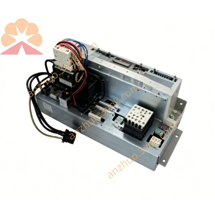
KUKA KPS-600 Robot Power Supply Module For KRC2 Controller Cabinet
Description
Model numbers: KPS‑600/20‑ESC, KPS‑600/20‑REL
Order numbers: 00‑104‑781, 00‑110‑728
Application: KRC2 cabinets for KR150 to KR300 heavy‑payload robots
Function: Main DC bus supply, control power supply, battery charging, brake energy management
2. Technical Specifications
Electrical Data
Input: 3∼ AC 400 V / 480 V (±10 %), 50 / 60 Hz
Rated current: 25 A (rms)
Peak current: 95 A (rms, 0.5 s cycle)
Output – Intermediate Circuit:
DC voltage: 565–585 V (continuous)
Rated current: 20 A
Peak current: 64 A
Output – Control Voltage:
24 V DC / 27 V DC, 30 A max
Power rating: Approx. 12 kW
Protection: Overvoltage, undervoltage, overcurrent, short circuit, overtemperature, ground fault, watchdog monitoring
Mechanical & Environmental
Dimensions (W × H × D): 200 × 120 × 100 mm
Weight: 4.7 kg (approx.)
Protection class: IP20 (for cabinet installation)
Operating temperature: 0 °C to +55 °C
Storage temperature: −20 °C to +70 °C
Cooling: Integrated forced‑air fan; maintain clear airflow (≥50 mm clearance)
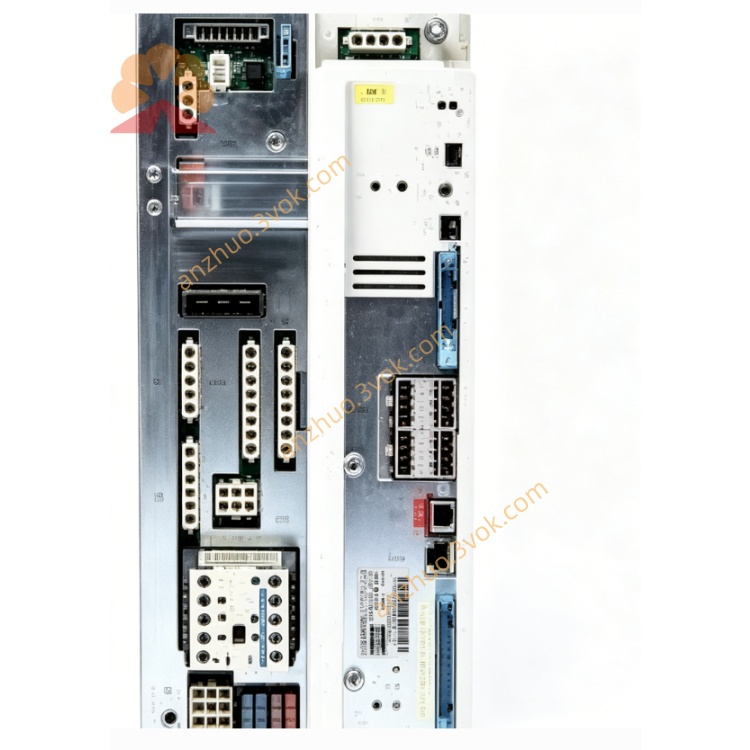
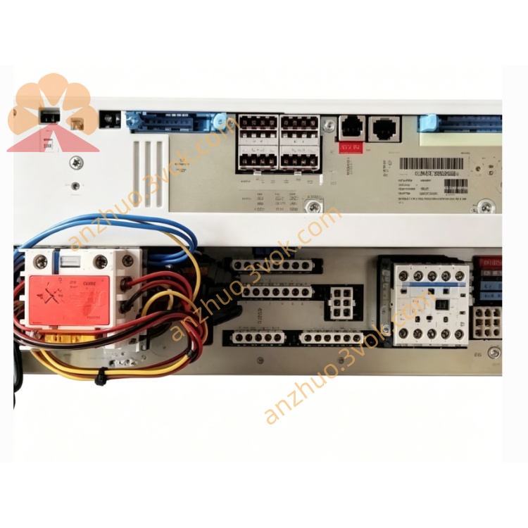
3. Connector Assignment
X1 – Mains Input
L1, L2, L3: Three‑phase AC
N: Neutral
PE: Protective earth
X2 – DC Intermediate Circuit
DC+: 585 V DC positive
DC−: 585 V DC negative
Connects to X1 of all KSD1 servo drives
X3 – Control Voltage
+24 V / 0 V: Control power for cabinet components
X4 – Battery & Brake
BAT+, BAT−: Battery charging (2 × 12 V lead‑acid)
BRK+, BRK−: External brake resistor connection
X5 – Servo Bus & Safety
IBS IN / OUT: Interbus servo bus (communication with KSD1 drives)
SAFE: Safety interlock signals (E‑stop, safety door)
4. LED Status Indicators (Front Panel)
- LED1 (Red) – Fault
Off: Normal operation
On: Critical fault (overvoltage, overtemperature, watchdog)
Flashing (3 Hz): Brake error
Flashing (6 Hz): Communication error
- LED2 (Green) – Power OK
Off: No power / processor inactive
Flashing (1.5 Hz): Intermediate circuit <60 V
On: Intermediate circuit >60 V (ready for operation)
5. Safety Instructions
High voltage hazard: DC intermediate circuit up to 585 V.
→ Wait at least 5 minutes after switching off the controller for capacitors to discharge before any wiring or maintenance.
Risk of electric shock: Only qualified personnel should perform installation or service.
Do not open, modify, or bypass internal components or safety circuits.
Ensure reliable protective earth (PE) connection for the cabinet, KPS, and all drives.
Keep ventilation slots free of dust and obstructions; inadequate cooling causes overheating.
6. Installation & Wiring
Mount the KPS‑600 vertically in the designated KRC2 cabinet slot.
Connect X1 to three‑phase mains (observe correct phase sequence and PE).
Wire X2 (DC+/DC−) to the DC bus distribution rail (connects to all KSD1 drives).
Connect X3 to the 24 V DC control distribution.
Attach battery cables to X4 (BAT+/BAT−) and brake resistor to BRK+/BRK−.
Connect servo bus IBS IN / OUT in daisy‑chain configuration with KSD1 drives.
Tighten all power terminals to 2.5 Nm torque.
7. Operation
Power‑on: After mains switch ON, internal charging circuit energizes the DC bus.
Standby: Green LED2 ON → DC bus ready; red LED1 OFF → no faults.
Drive operation: KPS supplies stable DC 585 V to KSD1 drives during all robot motions.
Regenerative energy: During deceleration, excess energy is dissipated via the brake resistor (monitored by KPS).
Fault response: Red LED1 ON; DC bus disabled. Read fault code via KCP teach pendant or WorkVisual.
8. Maintenance
Daily: Check LED status, fan operation, and cable integrity.
Weekly: Clean cooling fan and air vents; remove dust buildup.
Monthly: Retighten X1, X2, and X4 power terminals (2.5 Nm).
Quarterly: Verify battery charging voltage and brake resistor resistance.
Annual: Inspect electrolytic capacitors (bulging), fan wear, and perform full diagnostic test via WorkVisual.
Get a Quote