KUKA KPS-600 Industrial Power Supply Unit For KRC2 Robot Controller Cabinet
Description
Model:KPS‑600/20‑REL(standard)
Order No.:00‑110‑728
Application:KRC2 cabinets(KR150–KR300)
Safety:External safety relays(‑REL);integrated ESC(‑ESC)
2. Technical Specifications
Electrical
Input:3∼ AC 400/480 V ±10 %, 50/60 Hz
Rated current:25 A(rms)
Peak current:95 A(rms, 0.5 s)
DC Bus:565–585 V DC
Rated:20 A continuous
Peak:64 A
Control:24 V DC / 27 V DC, 30 A max
Power:~12 kW(6–8 axes)
Protection:OV/UV/OC/SC/OT/GF(‑REL);+ ESC watchdog(‑ESC)
Mechanical & Environmental
Dimensions:200 × 120 × 100 mm
Weight:4.7 kg
Protection:IP20(cabinet mount)
Temperature:0 °C to +55 °C
Cooling:Forced air fan(≥50 mm clearance)
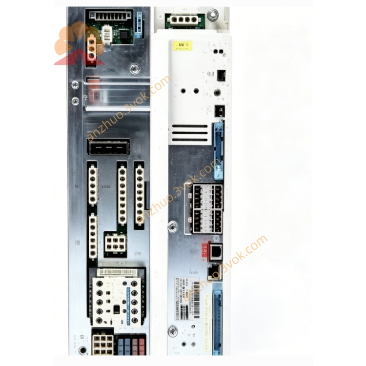
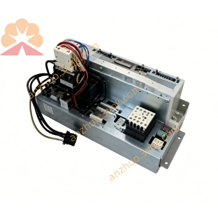
3. Main Components(KPS‑600 Internal)
Mains contactor
Rectifier & DC bus charging circuit
Brake control(6 axes + 2 external axes)
24 V/27 V distribution
Battery charging circuit
Safety logic:relays(‑REL)or ESC(‑ESC)
Interbus(IBS)interface to KSD1 drives
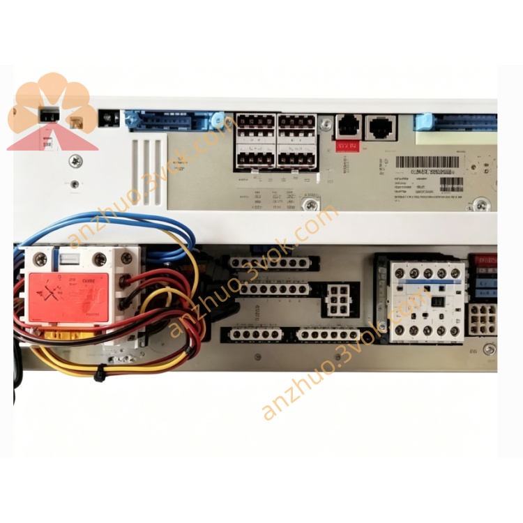
4. Connector Assignment(X1–X5)
X1 – Mains Input
L1/L2/L3:Three‑phase AC
N:Neutral
PE:Protective earth
X2 – DC Bus(to KSD1)
DC+:585 V DC positive
DC−:585 V DC negative
X3 – Control Voltage
+24 V / 0 V:Cabinet control power
X4 – Battery & Brake
BAT+/BAT−:2 × 12 V battery
BRK+/BRK−:External brake resistor
X5 – IBS & Safety
IBS IN/OUT:Interbus to KSD1 drives
SAFE:E‑stop/safety door(‑REL:relay contacts;‑ESC:dual‑channel)
5. LED Status(Front Panel)
LED1(Red)– Fault
Off:Normal
On:Critical fault(OV/OT/watchdog)
Flashing 3 Hz:Brake error
Flashing 6 Hz:Safety trip(E‑stop/door open)
LED2(Green)– Power OK
Off:No power
Flashing 1.5 Hz:DC bus <60 V
On:DC bus ready(>60 V)
6. Safety Instructions
High voltage:585 V DC. Wait ≥5 min after OFF for discharge.
Only qualified personnel may install/service.
‑REL:Safety relays must be wired dual‑channel.
‑ESC:Do not bypass ESC safety circuits(SIL2/PLd).
Keep vents clear;overheating causes shutdown.
7. Installation & Wiring
Mount vertically in KRC2 slot.
Connect X1 to 3∼ mains(check PE).
X2 → DC bus rail → KSD1 X1.
X3 → 24 V control distribution.
X4:battery + brake resistor.
X5:IBS daisy‑chain + safety wiring.
Torque power terminals to 2.5 Nm.
8. Operation
Power‑on:Mains ON → charge → DC bus ready(LED2 ON).
Standby:LED2 ON, LED1 OFF.
Motion:Supplies 585 V DC to KSD1 drives.
Regeneration:Energy dumped via brake resistor.
Safety stop:‑REL(20–50 ms relay delay);‑ESC(<10 ms STO).
9. Maintenance
Daily:LED status, fan, cables.
Weekly:Clean fan/vents.
Monthly:Retighten power terminals(2.5 Nm).
Quarterly:Check battery voltage & brake resistor.
Annual:Capacitor inspection, ESC diagnostic(‑ESC).
10. Troubleshooting(Common)
LED1 flashing 6 Hz:Safety trip → check E‑stop/door/X5 wiring.
LED2 flashing 1.5 Hz:DC bus low → mains/fuses/internal fuse.
LED1 ON(OV):Mains high, regenerative overload, or brake resistor missing.
LED1 flashing 3 Hz:Brake error → BRK wiring/resistor.
Overtemperature:Fan blocked, vents covered, or ambient >55 °C.
Get a Quote