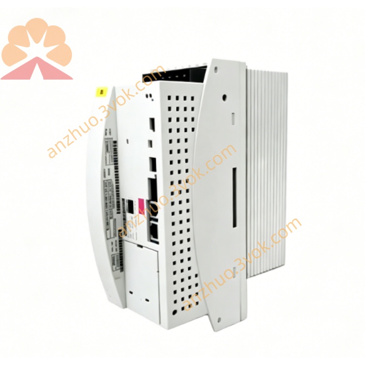
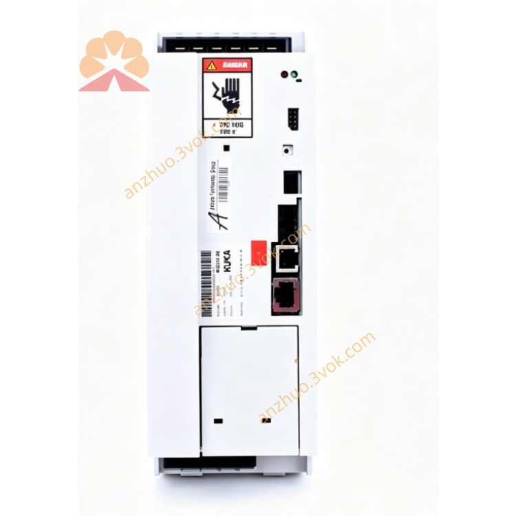
KUKA KSD1-16 KSD1-32 Servo Drive Amplifier For KRC2 Robot Controller
Description
2. Technical Specifications Comparison
KSD1-16
Rated output current: 8A
Peak current: 16A
Rated power: ~16kW
Intermediate circuit DC voltage: 0–770V DC
PWM frequency: 4kHz / 8kHz
Cooling: Built-in cooling fan
Width: 132 mm
Weight: approx. 3.2 kg
KSD1-32
Rated output current: 16A
Peak current: 32A
Rated power: ~32kW
Intermediate circuit DC voltage: 0–770V DC
PWM frequency: 4kHz / 8kHz
Cooling: High-power forced fan
Width: 176 mm
Weight: approx. 4.5 kg
Common Parameters
Installation: Cabinet vertical mounting, IP20
Operating temperature: 0°C ~ +40°C
Storage temperature: -20°C ~ +70°C
Control interface: Internal KUKA servo bus
Application: KRC1 / KRC2 robot controller main axes and external axes
3. Terminal & Interface Definition (Common for Both)
X1: DC intermediate circuit power + 24V control power, power/fault LED indicator
X2: Motor three-phase output, motor brake and encoder interface
X11: Safety signal & digital I/O interface (E-Stop, safety door interlock)
X13: Servo bus IN (signal input from upper level or previous drive)
X14: Servo bus OUT (signal output to next drive in daisy chain)
4. Main Features
High dynamic response, fast torque adjustment
Full protection: over current, over voltage, under voltage, over temperature, short circuit, encoder failure
Servo bus serial communication, automatic axis address identification
Compatible with KSS system software, parameter configured via KCP teach pendant or WorkVisual
Support robot joint axis and linear/rotary external axis
5. Safety Instructions
Internal high voltage up to 770V DC. After power off, wait at least 5 minutes for capacitor discharge before wiring or maintenance.
Do not disassemble, modify or short-circuit protection circuit.
Keep ventilation slots unblocked, reserved upper and lower cooling space ≥50mm.
All safety interlock signals must be connected correctly; do not bypass safety loop.
6. Installation & Wiring
Mount drive vertically inside KRC1/KRC2 cabinet.
Connect X1 to intermediate circuit DC power, strictly follow positive and negative polarity.
Connect X2 to motor power cable, brake cable and encoder cable with shield grounding.
Servo bus: X13 IN connected to previous drive or controller, X14 OUT connected to next drive.
X11 safety and I/O wiring use twisted pair cable, reliable grounding.
Cabinet, drive and motor must be connected to protective earth firmly.
7. Operation Description
After controller power-on, intermediate circuit voltage builds up automatically.
Drive power green LED on, red fault LED off means standby normal.
Under T1/T2 manual mode, enable allowing switch, robot can jog each axis normally.
In automatic mode, drive follows robot program to complete PTP/LIN/CIRC motion.
Once fault occurs, red LED lights up, drive locks output; read fault code via teach pendant to troubleshoot.
8. Daily Maintenance
Daily: Check power/fault LED status, cable appearance and tightness.
Weekly: Clean fan and dust filter, check ventilation.
Monthly: Retighten power terminals and connectors.
Quarterly: Backup drive parameters.
Annual: Check fan aging, capacitor bulging and abnormal noise.
9. Common Troubleshooting
No power LED: Check 770V DC intermediate voltage, cabinet fuse and KPS power supply.
Servo not ready: Check E-Stop reset, safety door interlock, motor and encoder cable.
Overload alarm: Too fast acceleration/deceleration, mechanical stuck or motor aging.
Overvoltage alarm: Regenerative energy abnormal, brake module failure or grid voltage unstable.
Bus communication error: Servo bus cable loose, drive address abnormal or drive damaged.
Get a Quote