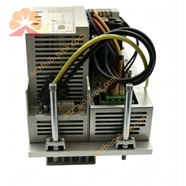
KUKA KPS-600/20-ESC Servo Power Supply Module For KRC2 Robot Controller Cabinet
Description
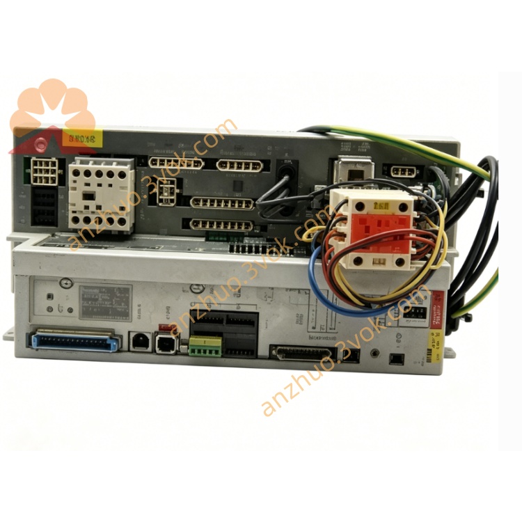
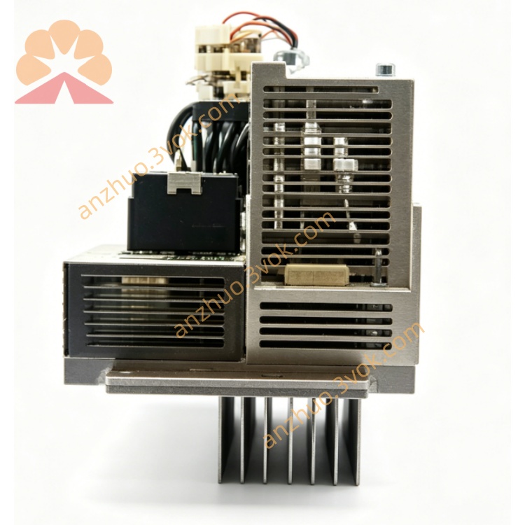
Model: KPS‑600/20‑ESC
Order No.: 00‑104‑781
Application: KRC2 cabinets for KR150 to KR300 heavy‑payload robots
ESC Function: Integrated dual‑channel safety, Safe Torque Off (STO), E‑stop/safety door monitoring
2. Technical Specifications
Electrical
Input: 3∼ AC 400 V / 480 V (±10 %), 50 / 60 Hz
Rated current: 25 A (rms)
Peak current: 95 A (rms, 0.5 s)
DC Intermediate Circuit:
Voltage: 565–585 V DC (continuous)
Rated current: 20 A
Peak current: 64 A
Control Output: 24 V DC / 27 V DC, 30 A max
Power Rating: Approx. 12 kW
Protection: Overvoltage, undervoltage, overcurrent, short circuit, overtemperature, ground fault, ESC dual‑channel watchdog
Mechanical & Environmental
Dimensions (W × H × D): 200 × 120 × 100 mm
Weight: 4.7 kg
Protection Class: IP20 (cabinet installation)
Operating Temperature: 0 °C to +55 °C
Storage Temperature: −20 °C to +70 °C
Cooling: Integrated forced‑air fan; ≥50 mm clearance required
Safety (ESC)
Safety Integrity: SIL2 / PLd (EN ISO 13849)
STO Response Time: <10 ms (electronic, no relay delay)
Monitored Signals: E‑stop, safety doors, drive enable, KCP 确认
3. Connector Assignment
X1 – Mains Input
L1, L2, L3: Three‑phase AC
N: Neutral
PE: Protective earth
X2 – DC Intermediate Circuit
DC+: 585 V DC positive
DC−: 585 V DC negative
Connects to X1 of all KSD1 servo drives
X3 – Control Voltage
+24 V / 0 V: Control power for cabinet components
X4 – Battery & Brake
BAT+, BAT−: Battery charging (2 × 12 V lead‑acid)
BRK+, BRK−: External brake resistor
X5 – Servo Bus & ESC Safety
IBS IN / OUT: Interbus servo bus (to KSD1 drives)
SAFE: ESC dual‑channel safety I/O (E‑stop, safety door, drive enable)
4. LED Status Indicators (Front Panel)
LED1 (Red) – Fault
Off: Normal operation
On: Critical fault (overvoltage, overtemperature, watchdog)
Flashing 3 Hz: Brake error
Flashing 6 Hz: ESC safety trip (E‑stop/safety door open)
LED2 (Green) – Power OK
Off: No power / processor inactive
Flashing 1.5 Hz: DC bus <60 V
On: DC bus >60 V (ready for operation)
5. Safety Instructions
High Voltage Hazard: DC intermediate circuit up to 585 V.
→ Wait at least 5 minutes after switching off for capacitors to discharge before maintenance.
Only qualified personnel may install or service this unit.
ESC Wiring: Dual‑channel wiring is mandatory for safety signals.
Do not open, modify, or bypass internal components or ESC safety circuits.
Ensure reliable PE connection for cabinet, KPS, and all drives.
Keep ventilation slots free; inadequate cooling causes overheating.
6. Installation & Wiring
Mount vertically in designated KRC2 cabinet slot.
Connect X1 to three‑phase mains (check phase sequence and PE).
Wire X2 (DC+/DC−) to DC bus distribution rail (KSD1 X1).
Connect X3 to 24 V DC control distribution.
Attach battery cables to X4 (BAT+/BAT−) and brake resistor to BRK+/BRK−.
Connect X5 IBS IN/OUT in daisy‑chain with KSD1 drives; wire ESC safety signals (dual‑channel).
Tighten power terminals to 2.5 Nm.
7. Operation
Power‑On: Mains ON → internal charging → DC bus energizes.
Standby: Green LED2 ON (DC bus ready); red LED1 OFF (no faults).
Drive Operation: Supplies stable 585 V DC to KSD1 drives during motion.
Regenerative Energy: Dissipated via brake resistor (monitored by KPS/ESC).
ESC Safety Response: On E‑stop/safety door open → STO activates → DC bus cut <10 ms → red LED1 flashes 6 Hz.
8. Maintenance
Daily: Check LED status, fan operation, cable integrity.
Weekly: Clean fan and vents; remove dust.
Monthly: Retighten X1/X2/X4 power terminals (2.5 Nm).
Quarterly: Verify battery charging voltage and brake resistor resistance.
Annual: Inspect capacitors (bulging), fan wear, full ESC diagnostic via WorkVisual.
9. Common ESC Faults & Troubleshooting
LED1 Flashing 6 Hz: ESC safety trip → check E‑stop, safety door, or X5 SAFE wiring.
LED2 Flashing 1.5 Hz: DC bus <60 V → check mains, cabinet fuses, or KPS internal fuse.
LED1 On (Overvoltage): Mains too high, regenerative overload, or brake resistor missing/faulty.
LED1 Flashing 3 Hz: Brake error → check BRK wiring or resistor.
Overtemperature: Fan blocked, vents covered, or ambient >55 °C.
Get a Quote